Announcement

Collapse
No announcement yet.

HP DPS-600PB 12V/24V 47A 1150W Power Supply Build Thread

Collapse

Zenm Tech Pte Ltd

Collapse

Visit Zenmtech at rc.zenmtech.com

X
 
  • Filter
  • Time
  • Show
Clear All
new posts

    #16
    CAUTION: Changes to Steps 4a - 4c of Modding - Part 1

    Post deleted - This portion was meant to supplement steps 4a - 4c of Modding - Part 1 but Moderator ZENM was kind enough to allow me to incorporate the changes into the original post so this section isn't required anymore.
    Last edited by yhchoong; 06-03-2013, 05:39 PM.

    Comment


      #17
      Originally posted by Kaen View Post
      Nice build log... unfortunately the last time I built a PSU was 20+ years ago...
      But I think I'll err on the side of caution and just buy one off the shelf.
      Thanks for the compliment, are you able to see the photos properly? Also, what you say is very true, and I only recommend this build thread for people who know what they are doing

      Comment


        #18
        Floating DC Ground (Skip this step for those who are only building a single 12V unit)

        At this point right now, we have a working 12V 47A 564W Power Supply. For those who do not need 24V capability and are just building a single 12V unit, please skip this step and proceed to Modding - Part 2.

        What we are doing in this section is to prepare the second power supply unit for series connection with the first one to obtain the full 24V. We will be essentially floating the DC ground of this particular unit by disconnecting it from AC ground. CAUTION: Only the second unit requires this mod. The first one does not!

        The purpose of this step is to allow us to connect both power supplies in series safely, without causing a short-circuit if the chassis of both power supplies were to touch together.

        Also, refer to the end of this section to see what floating DC ground means.

        Let's begin:

        Step 1a: DC Ground (JGND) is connected to AC ground through the chassis at these points (there are only 2 points, but they are located at both the top and bottom of the main board). We need to isolate them.

        Click image for larger version

Name:	IMG_2976.JPG
Views:	1
Size:	106.7 KB
ID:	974178


        What we are going to use are nylon screws, flanged washers and ring washers. Please get the exact same nylon screw because I'm not sure if other types will fit or are of sufficient length. They are again available from Bell Electronics at Sim Lim Tower Level 3. Only the flanged washer will be used in this particular step. Keep the nylon screw and ring washer for later.

        Click image for larger version

Name:	IMG_2959.JPG
Views:	1
Size:	225.3 KB
ID:	974199


        Insert the nylon flanged washer into the main board as shown:

        Click image for larger version

Name:	IMG_2967.JPG
Views:	1
Size:	234.0 KB
ID:	974179


        Do the same for the other corner:

        Click image for larger version

Name:	IMG_2970.JPG
Views:	1
Size:	116.0 KB
ID:	974180


        Step 1b: Sometimes, the fit may be too tight and the holes on the main board need to be enlarged ever so slightly:

        Click image for larger version

Name:	IMG_2966.JPG
Views:	1
Size:	131.0 KB
ID:	974181


        I am using a Dynamite Canopy Reamer for this:

        Click image for larger version

Name:	IMG_2965.JPG
Views:	1
Size:	100.1 KB
ID:	974182


        Do note that you can use the normal nylon ring washer instead of the nylon flanged washer as long as you use a nylon screw (at the later steps). I prefer to use the flanged washer simply because it looks nice and sit in the board tightly, not falling out during reassembly.

        Step 2 (VERY IMPORTANT): Test for continuity between JGND and the 2 points that are now covered by the nylon flanged washer using a digital multi-meter:

        Click image for larger version

Name:	IMG_2971.JPG
Views:	1
Size:	116.4 KB
ID:	974183


        Step 3: We have to trim down the standoff spacer. Note that with the nylon flanged washer on, the front right corner of the main board can no longer sit flush on the spacer, unlike the front left corner.

        Click image for larger version

Name:	1933.JPG
Views:	1
Size:	82.9 KB
ID:	974245


        This is because the back left and front right corners utilise a spacer type with a lip:

        Click image for larger version

Name:	1936.JPG
Views:	1
Size:	115.2 KB
ID:	974246


        While the back right and front left corners utilise a spacer type with no lip:

        Click image for larger version

Name:	1937.JPG
Views:	1
Size:	100.0 KB
ID:	974247


        Therefore, for the front right spacer, use a normal hand file or a dremel to sand it down and then smoothen out with grit 400 or 500 sandpaper. I used a dremel with sanding wheel for this.

        Click image for larger version

Name:	1934.JPG
Views:	1
Size:	91.3 KB
ID:	974248


        And the main board will now sit flush and parallel at the front:

        Click image for larger version

Name:	1935.JPG
Views:	1
Size:	77.0 KB
ID:	974249

        Also, I reassembled the main board just to illustrate step 3. Please do not reassemble yet as we still have to make use of an empty chassis for the next section on Modding - Part 2.

        Supplementary Information: So what exactly is floating DC ground?

        Well, think of it as 2 AA batteries in a flashlight, one on top of the other. We know that the voltage of a standard Energizer alkaline AA battery is 1.5V right? But 1.5V is actually the potential difference between the + and - terminals.

        A + terminal of 1.5V and a - terminal of 0V will of course give us a potential difference, or voltage of 1.5V.

        But how about the following cases?

        + terminal: 3V
        - terminal : 1.5V

        + terminal: 101.5V
        - terminal: 100V

        + terminal: 0.5V
        - terminal: -1V

        + terminal: 0V
        - terminal: -1.5V

        All of the above will give us a potential difference of 1.5V! However, for the sake of simplicity we generally assume that for the AA battery, it has a + terminal of 1.5V and a - terminal of 0V.

        So what happens if we connect 2 AA batteries together like in a flashlight? Does it short-circuit where the first battery connects to the second battery? The + terminal at 1.5V of the first battery is connecting to the - terminal of the second battery at 0V after all and the difference in voltage should cause a short... right?

        Click image for larger version

Name:	battery.jpg
Views:	1
Size:	14.4 KB
ID:	974197

        The answer is no. It will not short-circuit. This is because the batteries have a floating DC ground ie. the - terminal of the second battery on the right will now take on 1.5V, same as the + terminal of the first battery on the left. Furthermore, since the batteries have a potential difference of 1.5V, the second battery on the right will have a voltage of 3V at its + terminal:

        Click image for larger version

Name:	battery.jpg
Views:	1
Size:	14.2 KB
ID:	974198


        Floating DC ground means that the DC ground, or - terminal of the battery is not fixed to 0V. It will in actual fact, take on the voltage at the + terminal of the other battery as the point of reference.

        The same applies for our 24V power supply. The - terminal of our floating DC ground unit will take on the voltage of the + terminal on the non-floating unit at 12V. The + terminal of the floating unit will then be at 24V. If we did not float the DC ground by disconnecting it from AC ground, it will then take on the voltage of AC ground/Earth at theoretically 0V and that's when we will get a short and see sparks fly when we connect it to the other power supply and the chassis touch.

        1 step further:

        So hey, why not we float our AC ground too! Simply remove the earth terminal on our power cable into the wall socket right? This way, we don't have to disconnect DC ground from AC ground since DC ground will take on the voltage of AC ground, which is now floating. AC float, DC float, everything float and works, we gloat right?

        Well technically this is correct. But it's so very dangerous to do so. This is because if anything goes wrong with the power supply, it will no longer have a common ground with you. That means you and the chassis will be at different voltages and should the system malfunction such that the AC ground takes on 240V of our wall mains and the power supply offloads the full 47A into our body if we touch it accidentally, we will be badly hurt and electrocuted. Not good. So be really very careful here.

        Whew, enough of technical details. That's it for isolating/floating DC ground from AC ground for now.

        Last edited by yhchoong; 12-03-2013, 09:55 AM. Reason: Include explanation of Floating DC Ground

        Comment


          #19
          How to check for continuity

          Btw, please see this link to learn how to check for continuinty using a digital multi-meter.

          Comment


            #20
            Originally posted by yhchoong View Post
            Btw, please see this link to learn how to check for continuinty using a digital multi-meter.
            Hi
            just check on my Laptop, the picture trimming problem is only on the Ipad. Sorry, was reading the post on a ipad last nite. On the laptop it is fine.

            by the way, since you are building the power supply in series,( i don't understand about the term floating and stuff) is it possible for you to do it in such a way that it is easy to plug in and out 12v and 24v? because when charging big cell I want to use 24v. with smaller cell I want to stick to 12v. Possible to do that?

            Comment


              #21
              Originally posted by mave View Post
              Hi
              just check on my Laptop, the picture trimming problem is only on the Ipad. Sorry, was reading the post on a ipad last nite. On the laptop it is fine.

              by the way, since you are building the power supply in series,( i don't understand about the term floating and stuff) is it possible for you to do it in such a way that it is easy to plug in and out 12v and 24v? because when charging big cell I want to use 24v. with smaller cell I want to stick to 12v. Possible to do that?
              Phew, ok I won't worry about the photos then.

              The 24V supply I'm showing here is able to output 12V and 24V simultaneously to 2 different chargers in configuration 1, or output 2 x 12V in configuration 2. However, the maximum wattage output still remains at 1150W.

              For example, in configuration 1:

              I can connect a Powerlab 8 or i-charger 306b to the power supply at 24V and at the same time, and i-charger 106b at 12V. Both chargers are plugged in. The total current draw of both chargers cannot exceeed 47A however.

              This is a picture I got from another forum:

              Click image for larger version

Name:	Powering 306B from 24V and 106B+ from 12V #2.jpg
Views:	1
Size:	88.3 KB
ID:	974185


              In configuration 2 (It takes just a few seconds to switch from config 1 by shifting a wire. We are connecting DC ground back to AC ground and at the same time, making both power supplies function as single 12V units, just that they are physically next to each other):

              The power supply will now have 2 x 12V ouput, so you can connect 2 x i-charger 106b to it. Total current draw of both chargers cannot exceed 47A too.

              Comment


                #22
                Cool!

                Out curiosity, will it be possible to make use of the hotswappable connector instead of dismantling the whole power supply?
                i.e. buy the female end of the hot swap connector and work on that. and then add as many unit as you like. possible?
                (sorry don't have electrical background.)

                Comment


                  #23
                  Originally posted by mave View Post
                  Cool!

                  Out curiosity, will it be possible to make use of the hotswappable connector instead of dismantling the whole power supply?
                  i.e. buy the female end of the hot swap connector and work on that. and then add as many unit as you like. possible?
                  (sorry don't have electrical background.)
                  Yes it's possible if you can find it. The problem is I think it's proprietary and very hard to get from HP, while highly likely needing modifications at the same time.

                  You will then need to do the ribbon cable trick to switch the power supply on externally, ie. on the 9 pin array right at the front of the hot-swappable board. I can provide you with the schematics of which pins to conect together to swith the supply on.

                  What most people do is they solder the output wires/bullet connectors directly to the lugs on the hot swappable board. Visit this link to see how a guy in the US who makes and sells these supplies are doing it. I don't like it because the connectors are exposed, and there had been a 1-2 cases of an accidental short on the other forums.

                  Oh, if you want to add as many units as you like, you need to float them as well so disassembly is still required in the end.

                  I was very demoralised when I went on the other forums to see how people did theirs. They were in US and had these supplies available for cheap down there. If any screw ups happened, just buy another unit. It was that cheap. All they had to worry about were electrical shocks.

                  I spent 2-3 months of my year-end holidays (that's like all of it) 2 years ago daily on the forums and hands on learning, trying and experimenting before I built mine. I didn't know much about electrical devices then, and destroyed 1 power supply unit accidentally when I burnt a mainboard copper trace while trying to desolder a wire (the blue and purple one from the hot-swap board that you can simply cut off and heat shrink actually).

                  No one had a guide as detailed as the one I am writing right now and all assumed that you had some prior electronics knowledge. I didn't even know how to use a multi-meter then! So right now I'm doing this build thread trying to incorporate as much information I have as possible so that our bros need not go through the tedious amount of research and experimenting that I underwent myself. You do still need some basic electrical knowledge ie. know what is current, voltage and power as well as know how to not do anything too silly that you put yourself in danger.

                  Anyway, I'm sure you will be able to handle and build your own supplies just fine. Don't be daunted!

                  Comment


                    #24
                    Modding - Part 2

                    Modding - Part 2 will be all about making the aluminium faceplate mount for the Keystone binding posts. I know that not everyone will have a drill press or a chop saw or even a dremel. I did not have those tools myself before making my first power supply conversion. But I hope that this section will generate some ideas on alternate means to mount the binding posts.

                    Let's get started.

                    Step 1a: Using 3/4" x 3/4" x 26" aluminium angle from Jet hobby, measure out a 5.2 cm section and mark it out accordingly:

                    Click image for larger version

Name:	IMG_2983.JPG
Views:	1
Size:	111.4 KB
ID:	974217


                    Step 1b: Cut the angle to the marked out length. Note that I had to do a number of repeated cuts on each side by flipping over and repositioning the aluminium angle as my chop saw is too small to cut through 3/4" in a single pass.

                    Click image for larger version

Name:	IMG_2984.JPG
Views:	1
Size:	477.2 KB
ID:	974218


                    I am using a chop saw with 3rd party abrasive wheel (I recommend using the original carbide wheel but mine is blunt now) from Jet hobby for this purpose. It's not the most precise for repeatability but it will work for small scale projects. Also the cheapest chop saw at $59 you can find unless you want to fork out $200 for a professional Dewalt Miter Saw:

                    Click image for larger version

Name:	IMG_2989.JPG
Views:	1
Size:	113.8 KB
ID:	974219


                    CAUTION: Please take care of your personal safety when working with power tools. The chop saw is not difficult to use, but do wear eye protection goggles and a dust mask. The aluminium dust is very fine and once you breathe them into your lungs, they are there to stay forever, just like carbon fibre dust.

                    Since I had to do 2 units, I made a total of 4 x 5.2 cm faceplates. 2 working, and 2 spares:

                    Click image for larger version

Name:	IMG_2990.JPG
Views:	1
Size:	94.5 KB
ID:	974220


                    Step 2a: Clamp the faceplate onto the chassis using a G-clamp. The base of the faceplate will sit directly on top of the 2 metal stand-off spacers where the front mounting screws of the main board go into.

                    Click image for larger version

Name:	IMG_2991.JPG
Views:	1
Size:	66.1 KB
ID:	974221


                    I am using an Irwin 2" G-clamp but a cheap $2 one from Daiso will work fine here since not much force is necessary. Heck, even scotch-tape would probably work.


                    Click image for larger version

Name:	IMG_2998.JPG
Views:	1
Size:	123.1 KB
ID:	974222


                    Note that I aligned the faceplate so that it slightly protrudes out of the chassis:


                    Click image for larger version

Name:	IMG_2993.JPG
Views:	1
Size:	75.7 KB
ID:	974223


                    The faceplate should also be clamped more flush towards the right side of the chassis (yellow box) than the left side (red box) since a portion of the side chassis panel will slide into the gap on the left side during reassembly:

                    Click image for larger version

Name:	IMG_2994.JPG
Views:	1
Size:	62.0 KB
ID:	974224


                    Step 2b: Using a mechanical pencil with the pencil lead extended out quite a bit, mark out the drill placement spots by using the 2 screw holes as a guide. Be sure to draw the circle as accurately as possible by pressing the pencil lead firmly against the side of the screw hole. The more accurately you draw the circle the more accurate the placement of the drill holes.

                    Click image for larger version

Name:	IMG_2995.JPG
Views:	1
Size:	150.5 KB
ID:	974237


                    Step 2c: Now with a centre punch, indent the centre of the 2 circles which you have just drawn. I used a block of wood underneathe ($2 for a pack of 4 from Daiso) to help support the aluminium angle as I indented it.

                    Click image for larger version

Name:	1906.JPG
Views:	1
Size:	91.3 KB
ID:	974212


                    This is the automatic centre punch which I used (around $8). I got it from Horme Hardware at their Ubi Trade Center, which is like a giant supermarket for tooling and equipment. Most of your neighbourhood hardware stores should have it though:

                    Click image for larger version

Name:	IMG_2999.JPG
Views:	1
Size:	94.8 KB
ID:	974213


                    And this is how the faceplate should look like after you have indented it with the punch:


                    Click image for larger version

Name:	1907.JPG
Views:	1
Size:	85.0 KB
ID:	974214


                    Step 3: It's time to drill the mounting holes for the faceplate so that it can be bolted to the chassis. I am using a D&D Drill press - model number RDM-1601BN w/Laser guide. I got it from Horme Hardware (former Homely.sg) as well, for around $300:

                    Click image for larger version

Name:	1908.JPG
Views:	1
Size:	98.1 KB
ID:	974215


                    The drill bit I'm using is a unibit, or stepped bit. $50 from Horme. It makes short work of drilling bigger holes into metal:

                    Click image for larger version

Name:	1910.JPG
Views:	1
Size:	107.7 KB
ID:	974216


                    We are drilling holes of 2 mm diameter here. I'm using Mobil 1 10-30W ATF as a cutting fluid. And red electrical tape to prevent the vice from marring the surface of the aluminium angle. Here's the end result:

                    Click image for larger version

Name:	1911.JPG
Views:	1
Size:	102.3 KB
ID:	974225


                    Step 4: From the photo below, you can see that 3/4" x 3/4" aluminium angle is slightly too tall as a faceplate to fit the chassis properly. The next size down, 1/2" x 1/2" from Jet Hobby is unfortunately too small. So, it's time to grind down some aluminium angle with a dremel and grinding wheel. This is seriously the most time consuming and tedious part for a single step in the entire build.

                    Click image for larger version

Name:	1919.JPG
Views:	1
Size:	97.9 KB
ID:	974226


                    Mark out a line that is 1.7 cm from the very edge of the base of the faceplate as shown below. The excess portion at the top beyond the line is what we will have to trim or grind off.

                    Click image for larger version

Name:	1939.JPG
Views:	1
Size:	110.6 KB
ID:	974227


                    I am using a dremel with a sanding tip as shown below. Progress is very slow, and the aluminium angle heats up easily so frequent short pauses are required for it to cool down. You need to have a very steay hand and be meticulous. It does not have to be perfect though as rough edges can be sanded off later.
                    CAUTION: Please wear a dust mask and safety goggles again.


                    Click image for larger version

Name:	1945.JPG
Views:	1
Size:	117.6 KB
ID:	974228


                    Eventually, you will get something that looks like this:

                    Click image for larger version

Name:	1940.JPG
Views:	1
Size:	172.5 KB
ID:	974229


                    Notice the jagged and rough edges? Well they can be sanded off and polished to achieve a beautiful brushed finish, simply by using grit 400 or 500 sandpaper:

                    Click image for larger version

Name:	1942.JPG
Views:	1
Size:	162.3 KB
ID:	974230


                    Finally, the faceplate fits:

                    Click image for larger version

Name:	1944.JPG
Views:	1
Size:	73.8 KB
ID:	974231


                    Step 5a: It's time to determine the position of our binding posts. We have to trace out a piece of paper that is the exact same size as the faceplate (5.2 x 1.7 cm), and then temporarily glue/double-sided tape it down:

                    Click image for larger version

Name:	1947.JPG
Views:	1
Size:	187.1 KB
ID:	974232


                    Step 5b: We first have to mount the faceplate to the chassis properly. This is achieved using 2 different sizes of nylon washers (5 mm ID, 1 mm thick and 6 mm ID, 0.8 mm thick) as well as m3 nuts shown below. They are as usual, available from Bell Electonics, Sim Lim Tower Level 3. Prices as shown in the picture.

                    Click image for larger version

Name:	1960.JPG
Views:	1
Size:	127.3 KB
ID:	974233


                    I hope you did not discard the original 2 screws which held down the hot-swappable board! Put 2 x m3 nuts onto the screws as shown:

                    Click image for larger version

Name:	1962.JPG
Views:	1
Size:	126.5 KB
ID:	974234


                    Now for the larger size nylon washer (6 mm ID), cut off a portion of it using a pair of wire cutters as shown below. The amount that is cut off need not be very exact.

                    Click image for larger version

Name:	1964.JPG
Views:	1
Size:	134.4 KB
ID:	974235


                    Mount the faceplate by first sitting it into the metal standoff spacers of the chassis through the 2 mm holes we drilled earlier. This is then followed by the large nylon washer (note the orientation of the cut), the smaller nylon washer and finally the screws with the m3 nuts.

                    Click image for larger version

Name:	1967.JPG
Views:	1
Size:	192.3 KB
ID:	974236


                    Step 5c: Examine the Keystone 7019 dual binding posts carefully. They are available from RS Components Singapore, but not in stock locally. However, RS Singapore will bring them in with no extra charge. Shipping time is around a week. They are good for up to 30A and are the best I could find. In the photo below, notice the circular raised plastic edges as shown in the red box? We are going to make a recess in the faceplate for them to go, so the entire binding post unit does not slide around when bolted on.

                    CAUTION:
                    It is important they do not slide around such that the poles contact the aluminium faceplace. If not, this will cause a direct short-circuit.


                    Click image for larger version

Name:	1958.JPG
Views:	1
Size:	78.7 KB
ID:	974239


                    Using the back half of the binding post unit, align it onto the aluminium faceplate and trace an outline as shown. Note how the top portion is flush against the cooling fan part of the chassis, as denoted by the red box:

                    Click image for larger version

Name:	1951.JPG
Views:	1
Size:	95.8 KB
ID:	974238


                    Now, dip the back half of the binding post unit into a stamp pad ($3.20, from Popular). Following the outline we traced earlier, press the back half with the ink onto the faceplate so we get the locations of the two raised circular plastic portions:

                    Click image for larger version

Name:	1952.JPG
Views:	1
Size:	152.2 KB
ID:	974240


                    Remove the faceplate from the chassis. Next, using a circular template for 12 mm diameter circles, find the centre point of the ink circles. The ink circles are actually 12.3 mm in diameter but a 12 mm circular template will do just fine.

                    Click image for larger version

Name:	1953.JPG
Views:	1
Size:	121.1 KB
ID:	974241


                    Step 5d: Use a centre punch to indent the centre point as found in the previous step. The paper can now be removed and discarded:

                    Click image for larger version

Name:	1954.JPG
Views:	1
Size:	164.3 KB
ID:	974242


                    Finally, drill 13 mm diameter holes onto the faceplate to fit the binding posts. I am using my drill press with the stepped bit, which has a 12 mm portion with countersunk to make up for the slightly larger than 12 mm (ie. 12.3 mm) hole required. You may also want to oversize the hole a little (therefore 13 mm), so that you have a bit of leeway in positioning the binding posts to the exact spot you want.

                    Click image for larger version

Name:	1971.JPG
Views:	1
Size:	122.7 KB
ID:	974243


                    The hard work has paid off and the binding posts can now be mounted. Be sure to fit the included locking sun washers before tightening the nuts when mounting the binding post unit. Hardest part is done!

                    Click image for larger version

Name:	1973.JPG
Views:	1
Size:	171.7 KB
ID:	974244

                    Last edited by yhchoong; 10-03-2013, 05:43 AM.

                    Comment


                      #25
                      Modding - Part 3

                      Alright, we're onto the final lap - wiring up our binding posts. We have to create the wire connections themselves first.

                      I will be using 10 AWG wire throughout as it is more than sufficiently sized to handle the maximum output of our power supplies. Specifically, I am using Excellence branded 10 AWG wire from Rotor Hobby. It's quite a decent price at $5 I believe for 1 metre of red and 1 metre of black wire:

                      Click image for larger version

Name:	IMG_1724.JPG
Views:	1
Size:	186.2 KB
ID:	974250


                      Step 1a: Cut a length of the black wire around 4.4 cm long:

                      Click image for larger version

Name:	IMG_1726.JPG
Views:	1
Size:	196.0 KB
ID:	974251


                      Step 1b: Strip off the insulation such that the bare wire barely protrudes out of the cylindrical barrel of the ring terminal when fully inserted. The thin portion of the barrel will crimp onto the bare wire ends, while the thicker portion of the barrel will crimp onto the insulated wire. The knife in the photo points out the division between the thicker and thinner cylindrical barrels of the ring terminal:

                      Click image for larger version

Name:	IMG_1727.JPG
Views:	1
Size:	179.9 KB
ID:	974252


                      These are the 5 mm ring terminals that I am using. They are available from RS Components Singapore, stock number 681-4060. Note that they have the transluscent type of insulation. Alternatively, you can get the opaque type from Bell Electronics, Sim Lim Tower Level 3. Look for 5 mm diameter size, with yellow insulation for 10-12 AWG wires.

                      Click image for larger version

Name:	IMG_1725.JPG
Views:	1
Size:	153.1 KB
ID:	974253


                      Generally, the transluscent type of insulated ring terminals are of higher quality than the opaque type. However, both will work fine for our application since we are not doing highly corrosive off-shore marine type of wiring. The RS Component ones are really hard to crimp, even with the ratchet crimper which I am using (picture of tool in Modding - Part 1, Step 4a), such that I needed to use my drill-press vice to press down on the crimper's handles. If you do not have a table vice, please get the opaque ones from Bell Electronics.

                      Also, kindly read this link (if you haven't already earlier) on what makes a good crimp.

                      Here is a picture of how my own crimps look like after I cut them into two. Note how the copper of the wire looks like a continuous section instead of individual strands? That's the sign of a good crimp:

                      Click image for larger version

Name:	IMG_1737.JPG
Views:	1
Size:	107.8 KB
ID:	974254


                      Step 1c: Crimp the ring terminals onto both ends of the black wire at a 45 degrees angle as shown below. Please take note of exactly where the open end of the ring terminal barrel faces.

                      Click image for larger version

Name:	IMG_1740.JPG
Views:	1
Size:	119.1 KB
ID:	974255


                      Step 1d: Using a pair of pliers, bend the ring portion of both terminals at a 90 degrees angle. The bend should be away from the open end of the ring terminal barrel:

                      Click image for larger version

Name:	IMG_1742.JPG
Views:	1
Size:	120.3 KB
ID:	974257


                      Step 2a: Cut a length of the red wire around 8.8 cm long:

                      Click image for larger version

Name:	IMG_1743.JPG
Views:	1
Size:	189.9 KB
ID:	974256


                      Step 2b: Strip the insulation and crimp the ends of the red wire with the ring terminals, this time at a 180 degrees angle. Again, take note of the relative positions of the barrel. Then, bend the ring portion of both terminals like in Step 1d.

                      Click image for larger version

Name:	IMG_1747.JPG
Views:	1
Size:	180.3 KB
ID:	974258


                      Since I am converting 2 x power supply units for 24V, I made a pair of each:

                      Click image for larger version

Name:	IMG_1748.JPG
Views:	1
Size:	185.3 KB
ID:	974259


                      Step 3: They can now be attached to the binding posts and faceplate assembly. Note how I have angled the ring terminals. This will help it fit better into the chassis later during reassembly since space is very tight.

                      Click image for larger version

Name:	IMG_3076.JPG
Views:	1
Size:	96.0 KB
ID:	974275

                      Last edited by yhchoong; 12-03-2013, 09:37 AM.

                      Comment


                        #26
                        Reassembly with Binding Posts

                        Ok this is the last section - we are now going to reassemble the unit and incorporate the binding posts into it as well.

                        Step 1: Reattach the main board to the chassis casing.
                        This is essentially a reversal of steps found in Disassembly - Removing the Main Board, with the exception of the 2 key points below:

                        Key point 1: For those building the 24V power supply with floating DC ground for one of the units, do you remember the 2 nylon screws and washers which I talked about in step 1a of Floating DC Ground? We will have to use them to mount the 2 front corners of the main board, as shown below. Take note, this is only applicable for the unit with the floating DC ground mod.

                        Click image for larger version

Name:	IMG_3085.JPG
Views:	1
Size:	224.9 KB
ID:	974276


                        Key point 2: For those building the single 12V power supply, or the non-floating DC ground unit of the 24V power supply, we will use back the original screws:

                        Click image for larger version

Name:	IMG_3087.JPG
Views:	1
Size:	100.3 KB
ID:	974277


                        Step 2: Cut out a rectangular portion of the white cardboard so that we will have space to route the positive wire of the binding posts later on. The cut is around 1.2 cm deep, and almost across the entire breadth of the cardboard piece. It does not have to be very exact, all we need is just sufficient space for the wire to clear.

                        Click image for larger version

Name:	IMG_3091.JPG
Views:	1
Size:	177.5 KB
ID:	974278


                        Step 3: Attach the negative (black) wire of the binding post to the JGND outpost, and the positive (red) wire of the binding post to the J12V outpost. This is done by using the original screws obtained from the hot-swappable board removal to screw down the ring terminals onto their respective outpost.

                        Click image for larger version

Name:	IMG_3093.JPG
Views:	1
Size:	111.8 KB
ID:	974279


                        Do ensure that the ring terminals sit concentrically onto the outposts such that the surface to surface contact is the greatest. This is verified by having an equal spacing of ring terminal material all around the outpost screw. At the same time, take note that for JGND, I placed the binding post ring terminal in direct contact with the outpost, then finally the ribbon wire ring terminal on top of it.

                        Click image for larger version

Name:	IMG_3094.JPG
Views:	1
Size:	94.5 KB
ID:	974280


                        This is how the wires should be routed. As they are stiff and hard to get into place, I found that the easiest way is to route the negative (black) wire first so that it contours to its shape, then remove it from the outpost and do the same for the positive (red) wire, before routing both wires together. Please be careful of your own fingernails and the sharp edges of the chassis - they can easily snag and cut into the insulation of the wires while trying to bend them into shape.

                        Click image for larger version

Name:	IMG_3095.JPG
Views:	1
Size:	106.0 KB
ID:	974281


                        Also, take note of how the cooling fan cable is neatly tucked between the cardboard and the J12V outpost:

                        Click image for larger version

Name:	IMG_3096.JPG
Views:	1
Size:	94.8 KB
ID:	974282


                        Once the wires are in their final positions, the faceplate can be mounted to the chassis using the same method as seen in Step 5b of Modding - Part 2.


                        Step 4 (IMPORTANT): Let's do our final safety check by testing for continuity between the following points:

                        (a) Ensure that there IS continuity between JGND and the negative terminal of the binding posts, as well as J12V and the positive terminal of the binding posts:

                        Click image for larger version

Name:	IMG_3098.JPG
Views:	1
Size:	211.8 KB
ID:	974284


                        (b) Ensure that there is NO continiuity between the postive and negative terminals of the binding posts, as well as between JGND and J12V:

                        Click image for larger version

Name:	IMG_3097.JPG
Views:	1
Size:	101.0 KB
ID:	974283


                        (c) Ensure that there IS continuity between the chassis and the AC ground/earth pin of the IEC socket:

                        Click image for larger version

Name:	IMG_3099a.JPG
Views:	1
Size:	117.7 KB
ID:	974285


                        (d) For the unit WITH FLOATING DC GROUND, ensure that there is NO continuity between JGND/negative terminal of binding posts and AC ground/chassis.
                              For the unit with NO FLOATING DC GROUND, ensure that there IS continuity between JGND/negative terminal of binding posts and AC ground/chassis.

                        Click image for larger version

Name:	IMG_3100.JPG
Views:	1
Size:	185.8 KB
ID:	974286


                        At this point, proceed to step 5 for those building a single unit 12V power supply. Otherwise, proceed to step 6a for those building a 24V power supply.


                        *Step 5 (FOR SINGLE 12V POWER SUPPLY, SKIP FOR 24V POWER SUPPLY): You're almost done. All you need to do now is to reassemble the casing panels following the reversal of steps from the Disassembly - Removing the Casing Panels section and you're done.

                        Also, feel free to continue to Step 6a ONLY to tidy up the casing panels and add a fan guard and foam feet. Here's the end result - a working 12 VDC 47A power supply:

                        Click image for larger version

Name:	IMG_3113.JPG
Views:	1
Size:	115.4 KB
ID:	974305

                        Congratulations! You now have one of the best and most efficient power supply unit out there, comparable to or even better than Meanwell-branded supplies costing 2x to 3x more. Most importantly, you have gained new skills and knowledge in building your own unit, something which you can truly call your own

                        -----------------------------------------------------------------------------------------Completion of 12V Power Supply---------------------------------------------------------------------------------------


                        *Step 6a (FOR 24V POWER SUPPLY, OPTIONAL FOR 12V POWER SUPPLY): The catch for the quick release lever will get in the way when we attach the 2 HP units together for our 24V supply:

                        Click image for larger version

Name:	IMG_3103a.JPG
Views:	1
Size:	92.3 KB
ID:	974300


                        So what we have to do is to remove the entire lever, which are held onto the side panel by 2 rivets as shown:

                        Click image for larger version

Name:	IMG_3103b.JPG
Views:	1
Size:	75.7 KB
ID:	974301


                        The flanges of the rivets can either be drilled out, or grinded down with a dremel and sanding drum. One the flanges of the rivets have been removed the entire lever can be pried from the casing panel. It will simply pop off.

                        Click image for larger version

Name:	IMG_3103c.JPG
Views:	1
Size:	141.8 KB
ID:	974302


                        Finally, grind down the remaining stub edges with a small hand file as they are sharp:


                        Click image for larger version

Name:	IMG_3103e.JPG
Views:	1
Size:	99.8 KB
ID:	974303


                        The entire casing chassis can now be reassembled following the reversal of steps from the Disassembly - Removing the Casing Panels section.

                        Also, right before reattaching the cooling fan to the chassis, I added a fan guard which I got from Sun Light, Sim Lim Tower Level 3 (right in front of the ascending escalator). There are different sizes available - get the one for 40 mm diameter fans. It's a personal preference whether you want to add it or not, but I think it completes the look. Here's a side-by-side comparison picture between a unit without fan guard and another with the guard:


                        Click image for larger version

Name:	IMG_3105.JPG
Views:	1
Size:	104.5 KB
ID:	974304


                        I also recommend to add foam feet to the bottom as well. The power supplies, while not exactly heavy, will be well-protected from jolts with these feet when you set them down hard. You don't have to get the expensive 3M-branded ones. I'm using feet purchased from the Value $ store that is available at many heartland shopping centres. $1.05 for quite a variety:

                        Click image for larger version

Name:	IMG_3143.JPG
Views:	1
Size:	136.7 KB
ID:	974315


                        And this is how I attached them to the chassis:

                        Click image for larger version

Name:	IMG_3144.JPG
Views:	1
Size:	109.2 KB
ID:	974316


                        Step 6b (FOR 24V POWER SUPPLY, NOT FOR 12V POWER SUPPLY): We have to create our final wire jumper to connect both units in series togther, as shown in the red box:

                        Click image for larger version

Name:	IMG_3142.JPG
Views:	1
Size:	99.6 KB
ID:	974318


                        This part is a little tricky because for the Keystone Binding Posts, the caps do not unscrew totally so we either have to modify ring terminals (green box), or use shortened fork terminals (red box). Modified terminals are placed at the top row while the originals are at the bottom. Also, note the sizes of the ring terminals - they are meant to fit 5.5 mm - 6 mm diameter posts and 10 - 12 AWG wires. The ring terminals are once again available at Bell Electronics, Sim Lim Tower Level 3. As for the fork terminals, they are available at Sin Li Electronics Trading, Sim Lim Square Level 2. I prefer to use the fork terminals as they have a larger contact surface area. With that said, the ring terminals work well too and I am using them on my personal 24V unit.


                        Click image for larger version

Name:	IMG_3133.JPG
Views:	1
Size:	86.1 KB
ID:	974317


                        While it's evident why I had to modify ring terminals to fit them onto the binding posts, the reason why I shortened the prongs of the fork terminals is because when you put them onto the binding posts, a small part of the prongs protrude out (green box) and that's a short-circuit accident waiting to happen:

                        Click image for larger version

Name:	IMG_3134.JPG
Views:	1
Size:	88.5 KB
ID:	974319


                        So here are the dimensions to shorten them to (pardon the amateur drawing):

                        Click image for larger version

Name:	IMG_3153.JPG
Views:	1
Size:	79.4 KB
ID:	974320


                        I used a Dremel with cutting wheel to shorten the prongs. Note that this will expose the copper core of the terminal (red box):

                        Click image for larger version

Name:	IMG_3136.JPG
Views:	1
Size:	134.4 KB
ID:	974321


                        Since copper corrodes easily, I then re-tinned the exposed copper tips with a 100W soldering iron. The metal clip serves 2 purposes - it holds the fork terminal in place for re-tinning and acts as a heat sink to wick away the excess heat from the iron so that the yellow insulation jacket does not burn.

                        Click image for larger version

Name:	IMG_3141.JPG
Views:	1
Size:	68.6 KB
ID:	974322


                        Next, prepare a 8.5 cm length of 10 AWG wire and crimp the shortened fork terminals on both ends:

                        Click image for larger version

Name:	IMG_3139.JPG
Views:	1
Size:	142.0 KB
ID:	974323


                        [B]Finally, use the new jumper wire to connect the POSITIVE TERMINAL OF THE NON-FLOATING DC GROUND UNIT TO THE NEGATIVE TERMINAL OF THE FLOATING DC GROUND UNIT.

                        We are done - 24V, 47A and 1150W of power!

                        Click image for larger version

Name:	IMG_3145.JPG
Views:	1
Size:	122.5 KB
ID:	974324


                        And bench-testing with my PowerLab 8 on my TX 3s Lipo battery:

                        Click image for larger version

Name:	IMG_3147.JPG
Views:	1
Size:	121.2 KB
ID:	974325


                        Everything works! 
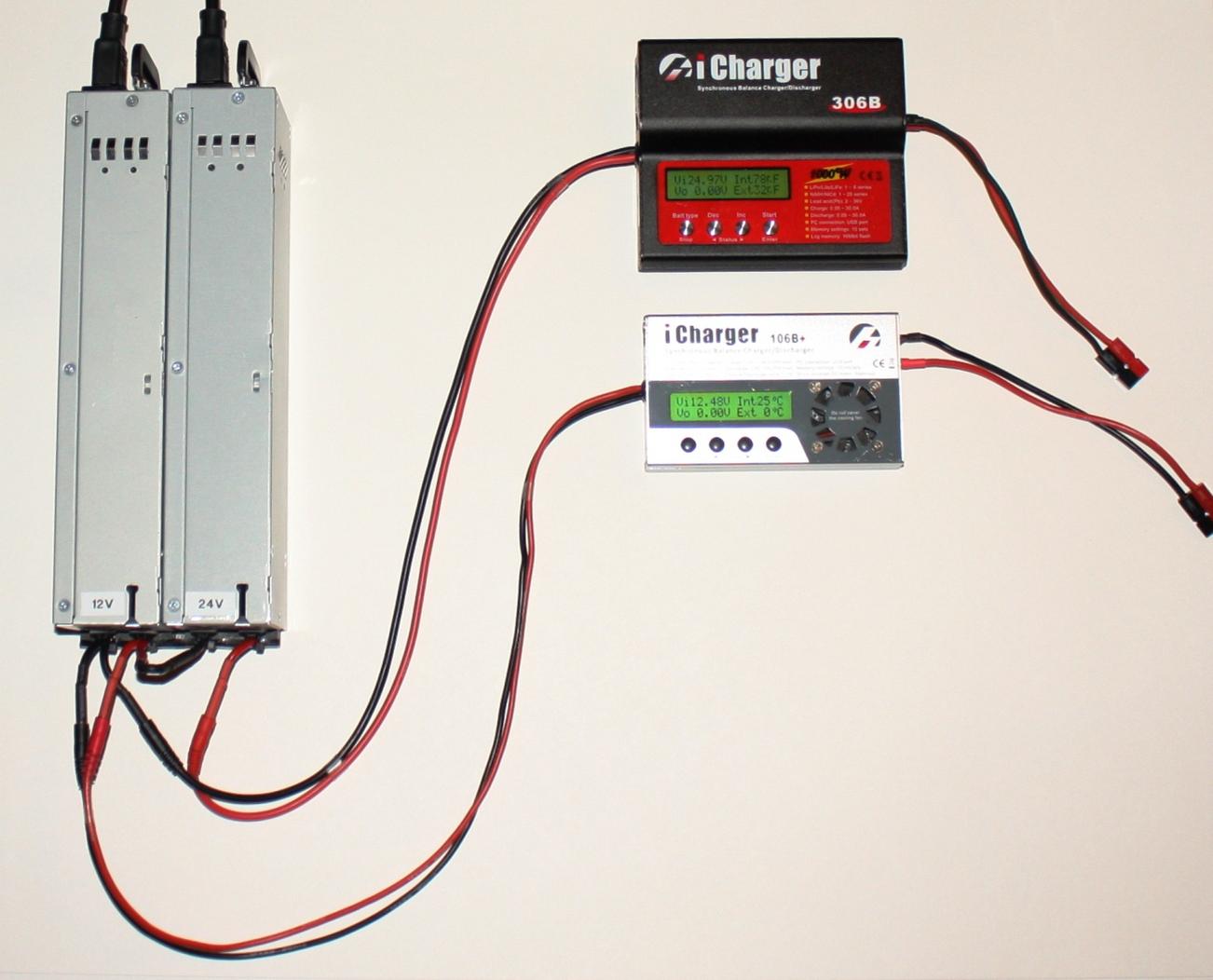
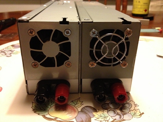
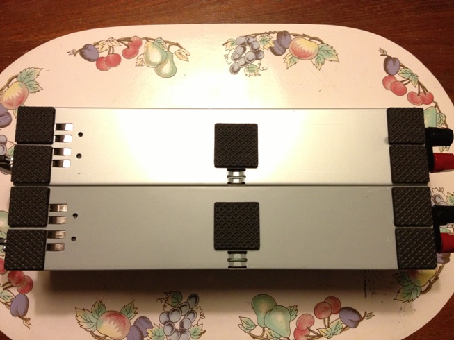
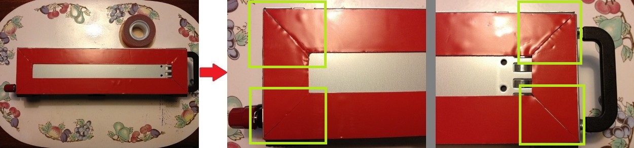
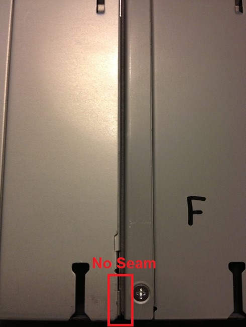
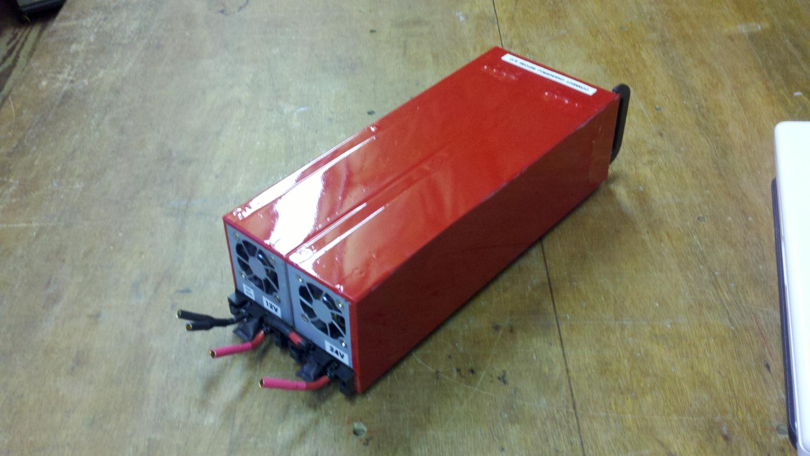
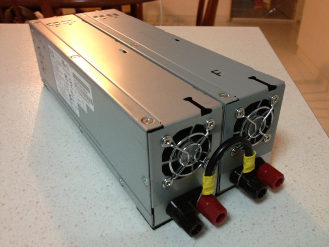
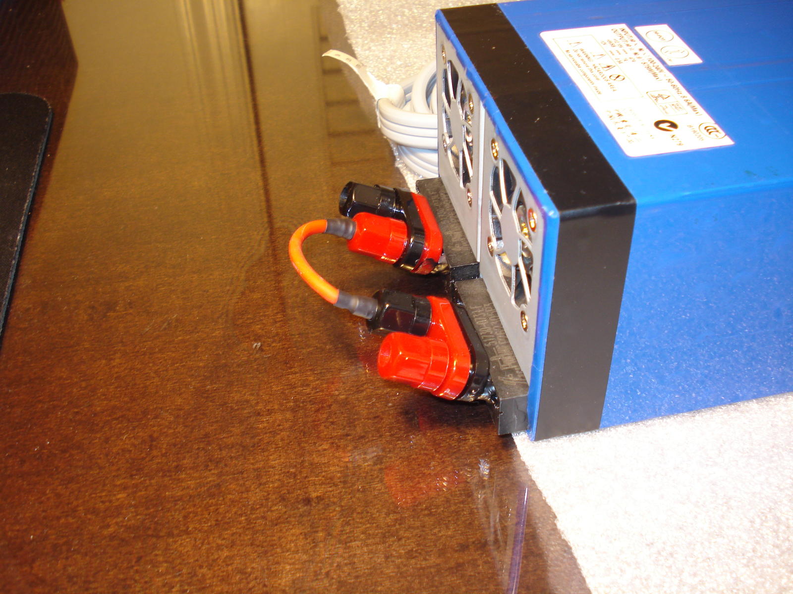
Now, let's join the 2 units physically together using the RC hobbyist's bandaid - 3M 4011 mounting tape. The reason why I did not do this step much earlier is because had anything went wrong during testing, I could at least still open up the units easily without having to remove and waste the tape.

                        Note how I had cut the tape ends at a 45 degrees angle so that the edge of the tape strips can be hidden at the corners:

                        Click image for larger version

Name:	IMG_3148.JPG
Views:	1
Size:	119.3 KB
ID:	974326


                        The grey colour of the 3M 4011 tape matches the chassis perfectly. You also won't be able to tell where the seams of the tape strips are.

                        Click image for larger version

Name:	IMG_3151.JPG
Views:	1
Size:	77.1 KB
ID:	974327


                        [OPTIONAL] If you are handy with a covering iron and heatgun, you can even wrap ultracote around the units for a professional look:

                        Click image for larger version

Name:	Ultracote.jpg
Views:	1
Size:	134.8 KB
ID:	974328


                        And lastly, a beautiful shot of our hardwork:

                        Click image for larger version

Name:	IMG_3152.JPG
Views:	2
Size:	107.3 KB
ID:	974329


                        Well, that's it people. This thread is where 2 weeks of my holidays went to. I realised that the thread has a lot of views but not much comments, but maybe I'm too long-winded haha. However, I just wanted to make sure that every step is done in full detail along the way so there is no ambiguity. While the entire build may look intimidating at first, it is actually not. No soldering was required, and I believe the drill press can be replaced with a hand drill and very steady hand. Just take it 1 step at a time and you will be building your own power supply unit in no time.

                        I will put the newly-built power supply in this thread on sale in the buy/sell forum at $150. I think I spent in excess of $120 for raw cost so an additional $30 for labour would be very nice, which probably boils down to a rate of $1.50/hour or so

                        Good luck and remember to have fun people!

                        Last edited by yhchoong; 15-03-2013, 11:29 PM.

                        Comment


                          #27
                          Very nice work you've got there. I'm sure many members of DH appreciate it, and are busy making one for themselves, and have no time to comment on this thread?

                          Anyway, I tried doing this as well, and it really helped to have everything step by step. Your instructions were really clear, and the photos were of great help!

                          I did mine the same way as yours, except for the binding post part. What I felt was insufficient, was the 30A binding post. It seems like it wouldn't be able to handle the current.

                          I searched on RS, and I found these:

                          Binding post (Red)
                          Binding post (Black)

                          Looking at the datasheet, it handles up to 35A, and is a tad more expensive than the binding post you originally proposed.

                          Being the perfectionist that I am, I didn't like the fact that the binding post would be the weakest link in the system, and I really wanted something that could handle the current. Since most chargers (high powered ones) use banana plugs for input (although I don't think it's the best choice out there), we could just use female 4mm bullet connectors. 4mm Bullets are theoretically rated at 60A (according to Zen at this thread) or 93A (as stated by Hobbyking, which probably fudged the numbers).

                          Be it fudged or unfudged or vanilla, 60A is still way higher than the 30/35A of the binding posts, and would eliminate potential weaknesses in our system. We could just squeeze two of the 4mm female connectors into the housing provided by HK and then plug or chargers right into it.

                          Also, the 10AWG wires at Rotor are real cheap at $5. HK sells them at USD 2.99 per metre, excluding shipping.

                          Anyway, thanks a lot for this build thread! You'll save us some holes in our pockets.

                          Comment


                            #28
                            Originally posted by perdification View Post
                            Very nice work you've got there. I'm sure many members of DH appreciate it, and are busy making one for themselves, and have no time to comment on this thread?

                            Anyway, I tried doing this as well, and it really helped to have everything step by step. Your instructions were really clear, and the photos were of great help!

                            I did mine the same way as yours, except for the binding post part. What I felt was insufficient, was the 30A binding post. It seems like it wouldn't be able to handle the current.

                            I searched on RS, and I found these:

                            Binding post (Red)
                            Binding post (Black)

                            Looking at the datasheet, it handles up to 35A, and is a tad more expensive than the binding post you originally proposed.

                            Being the perfectionist that I am, I didn't like the fact that the binding post would be the weakest link in the system, and I really wanted something that could handle the current. Since most chargers (high powered ones) use banana plugs for input (although I don't think it's the best choice out there), we could just use female 4mm bullet connectors. 4mm Bullets are theoretically rated at 60A (according to Zen at this thread) or 93A (as stated by Hobbyking, which probably fudged the numbers).

                            Be it fudged or unfudged or vanilla, 60A is still way higher than the 30/35A of the binding posts, and would eliminate potential weaknesses in our system. We could just squeeze two of the 4mm female connectors into the housing provided by HK and then plug or chargers right into it.

                            Also, the 10AWG wires at Rotor are real cheap at $5. HK sells them at USD 2.99 per metre, excluding shipping.

                            Anyway, thanks a lot for this build thread! You'll save us some holes in our pockets.
                            Hi there perdification, thanks for the feedback, I appreciate it! I'm simply hoping that I did not scare people off the build by the use of less common home tools like a drill press and mini chop saw haha.

                            I saw the data sheet of the binding posts that you linked and I understand your concerns. They were the exact same concerns that I had as well when I did my first supply, because safety is paramount. However, I talked to people on the other forums who have used them successfully. Specifically, if you search for akschu on RCGroups who sold dropped in replacement faceplates in the past using the Keystone 4019 as the binding posts, he had actually pulled 50 A through the Keystone 4019 with no detectable rise in temperature. Browsing around, you find that people are using in cheaper Ebay binding posts at 4 sets for $3 and fingers-crossed, they have all been working well. I'm certainly not going to even give those Ebay binding posts a chance though, far too risky.

                            Also to put it this way, 35A of the PKI 10A and 30A of the Keystone 4019 may simply be a matter of the manufacturer overstating / understating testing specs. Had 33A been the actual amperage rating of either binding posts, the PKI 10A may have it rounded up to 35A while the Keystones rounded down to 30A. Regardless they are all between the 30-40A benchmark.

                            More importantly, to look at the full picture, do take into account the rated voltage as well. The Keystones are rated for up to 30 A while having 1000 VAC through it, while the PKI 10A is rated for 35 A while having 60 VDC through it. That's a huge gap right there if you are taken into account the overall functional quality ie. wattage rating of the binding posts as a whole.

                            Lastly, the binding posts are 4 mm female bullet connectors, ring/fork terminal connectors and bare wire connectors all rolled into one You can plug in a 4 mm male bullet through the front end of the posts, just like this pic I got off RCG (I don't like the way the binding posts are attached though):

                            Click image for larger version

Name:	banana plugs.jpg
Views:	1
Size:	242.5 KB
ID:	974344


                            So if a regular female bullet connector is rated at 60A-90A, then surely our Keystone or PKI 10A by sheer virtue of size and volume of conductive material must be rated at least equal to or higher than that?

                            Of course it's so much easier to just solder on bullets without even removing the hot-swappable board. That would save us so much time and effort. No breathing in of aluminium dust and numb fingers from all the drilling and grinding too haha. But I went with binding posts mostly because I wanted to use ring terminals. They do not lose the tension in the leaf springs like the banana connectors, have more surface area, and do not degrade over time from frequent insertion and removal.

                            Most importantly, not all banana/bullet connectors are created equal, which is what led Revolectrix to use a custom longer length 4mm banana plug for their MPA parallel charging boards:

                            Click image for larger version

Name:	MPA.jpg
Views:	1
Size:	66.4 KB
ID:	974345


                            Had regular 4mm banana plugs been sufficient for the 40A rating of the MPA board, I doubt Revolectrix would have gone the extra mile to integrate a custom one into their board.

                            Ah here I go being long-winded again. So my bottomline is even in the professional industries, there are different levels of agreement as to the "correct" amperage rating of these connectors. However the laws of physics do not change - if the connector has more surface area and volume, then its resistance is going to be lower than that of a similar material connector which is physically smaller with less contact area, thus giving the larger connector a higher current carrying capability.

                            Hope my thoughts are useful to you, good luck with the build and don't worry about the binding posts!

                            Comment


                              #29
                              Thanks for the explanation! It sure made things clearer. Well, I presume that if the datasheets are from the manufacturer and RS sells them, the products should conform reasonably to the specs in the datasheet. That's just my unjustified assumption though, gut feeling. That doesn't mean to say that I trust the data 100%, but I would trust it more than those on eBay.

                              For me personally, I'd just use 4mm bullets, it's much cheaper than the binding posts and serves the same purpose.

                              Great job anyway, and hope to see more people commenting!

                              Comment


                                #30
                                Hi,

                                how about doing another round with HP proliant dps-1200fb?
                                Any idea how to do that?

                                Comment

                                Working...
                                X