Juz did my own 12V DC Regulated PS with a P4 ATX PS i found!
Some guy threw away a CPU casing with the P/S inside..
So i took out the PS and dumped the casing! hehe..
Here are the items i got from SLT.
1 x 10ohm 10W sandbar type resistor
2 x RED terminal post
1 x BLACK terminal post
1 x SPST switch
1 x Blue bright LED
Well, i didn't do the dirty work, my dad did it for me.
I juz guided him along, he's a qualified electrician and solder much better!
Here are the steps..
0. Try to clear the power left in the capacitor (if any). Use bulbs or ammeter to check.
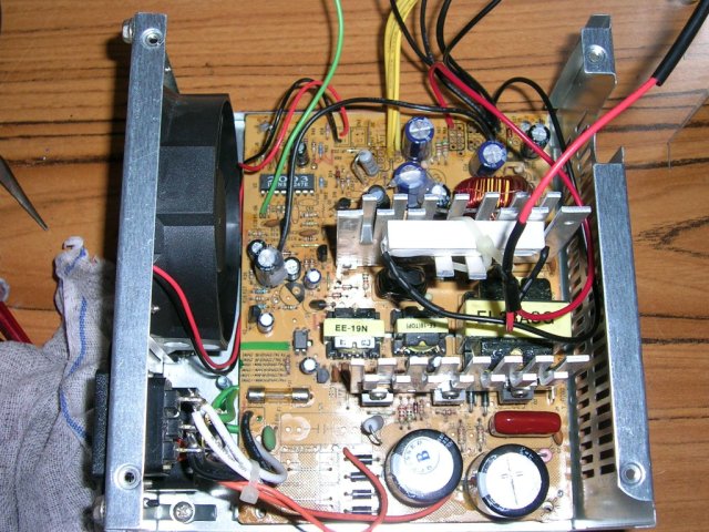
1. Open up the P/S, removed all unused wires.
2. Keep only red (+5), yellow (+12), black (ground), green (PS_ON), and any other wires u want to play with.
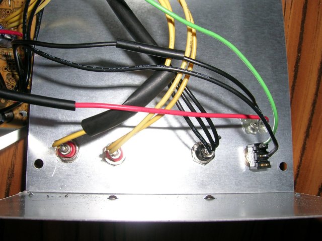
3. Drill holes on the casing, mount the posts. I had 2 12V post and 1 0V post.
4. Connect the +5V to the postive pin of the LED. And the ground wire to the negative pin of the LED.
5. Connect the +5V to the resistor and negative wire to the other pin. (To load the P/S for stable o/p).
6. Connect (solder) half the yellow wires to 1 12v and the rest of the yellow to the other 12v post.
7. Connect the green wire n 1 negative wire to the switch. How? If u dunno, u SHOULD NOT be attempting tis mod!
8. Close back the P/S and u're ready to rock!
Here's some links for additional reading (strongly encouraged!)
Problems:
Only problem i had was that i must connect the charger to the P/S and then turn it on
If i on the P/S and connect the charger to it, it will auto-shutdown..
weird problem, i do not know why also.. but it works well this way too..
measure the output to be about 12v, dun have a DMM to check.. using analog MM.
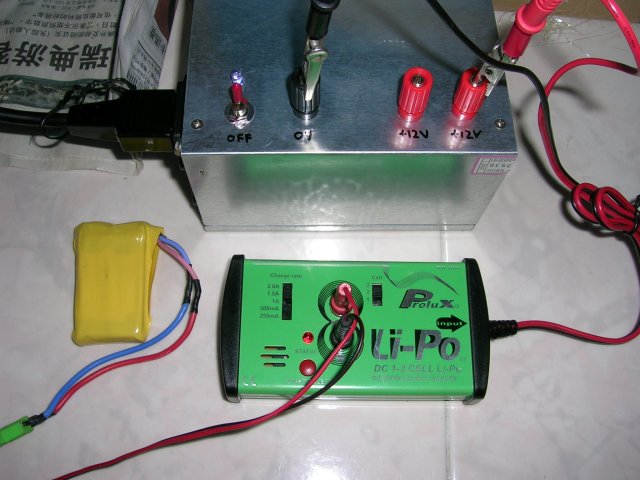
Charged a 2s lipo using the prolux 3834 without any problems.
Pictures follows.
Cheers.
I tied the resistor to one of the heatsinks to help dissipation.
2 red, 1 black post, 1 switch and the led above the switch.
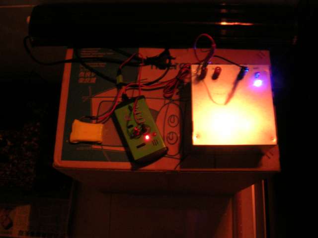
New P/S in action!!
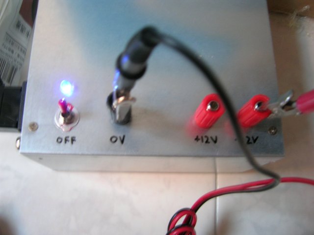
I love blue leds!! Looks damn cool charging at nite!
Some guy threw away a CPU casing with the P/S inside..
So i took out the PS and dumped the casing! hehe..
Here are the items i got from SLT.
1 x 10ohm 10W sandbar type resistor
2 x RED terminal post
1 x BLACK terminal post
1 x SPST switch
1 x Blue bright LED
Well, i didn't do the dirty work, my dad did it for me.
I juz guided him along, he's a qualified electrician and solder much better!
Here are the steps..
0. Try to clear the power left in the capacitor (if any). Use bulbs or ammeter to check.
1. Open up the P/S, removed all unused wires.
2. Keep only red (+5), yellow (+12), black (ground), green (PS_ON), and any other wires u want to play with.
3. Drill holes on the casing, mount the posts. I had 2 12V post and 1 0V post.
4. Connect the +5V to the postive pin of the LED. And the ground wire to the negative pin of the LED.
5. Connect the +5V to the resistor and negative wire to the other pin. (To load the P/S for stable o/p).
6. Connect (solder) half the yellow wires to 1 12v and the rest of the yellow to the other 12v post.
7. Connect the green wire n 1 negative wire to the switch. How? If u dunno, u SHOULD NOT be attempting tis mod!
8. Close back the P/S and u're ready to rock!
Here's some links for additional reading (strongly encouraged!)

Problems:
Only problem i had was that i must connect the charger to the P/S and then turn it on
If i on the P/S and connect the charger to it, it will auto-shutdown..
weird problem, i do not know why also.. but it works well this way too..
measure the output to be about 12v, dun have a DMM to check.. using analog MM.
Charged a 2s lipo using the prolux 3834 without any problems.
Pictures follows.
Cheers.
I tied the resistor to one of the heatsinks to help dissipation.
2 red, 1 black post, 1 switch and the led above the switch.
New P/S in action!!
I love blue leds!! Looks damn cool charging at nite!


Comment