All of them are of the same colour. Mine is the cheaper ones, I bought at $39. Don't think these have right?
-
-
As I said, look at the sticker on the power supply. If it indicate like Rail #1 and #2 or +12V1 and +12V2, then it is multi rail. If not, then it is a single rail. U can connect all yellow wire together.
To be double confirm, measure the voltage of all yellow wires. If it give u the same voltage, them confirm. U want to even double confirm, u can measure the resistance of all yellow wires (measure with power supply turn off). If they are all in 0Ohm, them it is single rail type.
BTW, u sure your $39 PSU can supply 20Amp of 12V?
SHComment
-
At least thats what its stated for the +12V.
+5VSB - 2A - Purple
+12V - 20A - Yellow
+5V - 26A - Red
+3.3V - 27A - Orange
-12V - 0.3A - Blue
-5V - 0.3A - White
P.G - -- - Gray
On/Off - -- - Green
Not able to find any stating different values for Rail #1 or #2.
Guess should be correct. I'll shrink tube every single wire not required and leave the rest outside. Now run out of tubes so have to hold on it for a while.
Update again later.Comment
-
OK. So it should be single rail type of PSU.
SHComment
-
electronic shop
Guys, where can I buy 10W resistor? Is it only in Sim Lim?
Thankssigpic
"Sky's the limit"Comment
-
ATX Power Supply
Tried CellPro 10S to charge a 6S LiPo at 4A, and saw on the charger display that it consumes 11A from the power supply. It means that this design could sustain that 11A of current. Never tried charging at 5A to see if the power supply could sustain the CellPro 10S...
see this link... http://www1.rcphilippines.com/forum/...p?topic=2720.0sigpic
"Sky's the limit"Comment
-
Please advise what is the minimum Amp PSU for the Hyperion EOS0615 DUO 3, if i'm charging 6S Lipo for each of the 2 port?
Can i use the wall charger for 12V Lead Batt, to act as a PS?
Many Thanks.Comment
-
Procedure
1. Short the green wire to black wire.
2. Between red wire and black wire, connect a high-wattage resistor (eg. 2.7 ohms, 10W)
3. Red wire for the positve terminal of the charger, and black wire for the other terminal of the charger.
Here's a little consideration on choosing the load resistor, "be sure that the power given by the ATX @ 5V (red) is smaller than the power rating of the load resistor you use".
In my own design, I connected 2 parallel load resistors to have a greater load curent. see attached

I even placed the 2 load resistors at the fan-out as cooling, and on the ATX casing as the heat sink.

I used 6 wires each for the +12V and GND going to my charger. Why? Because the current flowing is so high that could generate a voltage drop, and will end-up lesser voltage at the terminal of your charger. So we need to decrease the wire-resistance through parallel connection.

At no load, or shall we say I haven't connected the ATX PSU to a charger running, I got this measurement.

Then I tried putting electronic load at my PSU to see the maximum load current it can sustain, wherein the PSU output voltage is not lesser than 12V. I got this measurement.
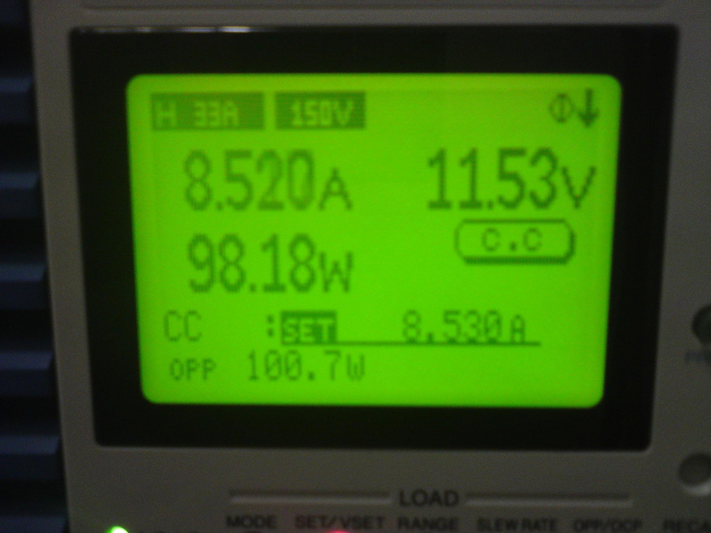
My PSU can sustain 8.5 Amps at 12V output. But, since this is an electronic load, I know it can even surpass that 8.5 Amps when I use it for my charger.
P.S.
I could even connect 1 more resistor to make it 3 to increase my load, and somehow lift-up the output voltage.
Iload = 5.5556 A (@ 3 parallel resistor)
Power on each resistor = 9.2593 W, same power dissipation with the 2 parallel resistors.
Note: I tried computing with 4 or 5 parallel resistors (2.7-ohm, 10W), the power dissipation still 9.2593 < 10Wsigpic
"Sky's the limit"Comment
-
Actaully, why do you need to put resistors? Mine worked fine without resistors.Comment
-
Food for thought here,
If you are using a PC PSU, the power rating of cheap PSU are often misleading.
A lot of time, it is not able to sustain high power loading for an extended time, which is required for the charging of a battery like 2 x 6s ie 3000mHA @ 2c which will need a constant 266 Watt of power.
A true to specification ATX 2.1 PSU should perform at a constant 12V/19A max per rail +-5% variance for extended period. So by specification, a serial of 2 Rail would be able to provide 24V/19A and charge a 2 x 6s 3000mHA @ 4C without issue.
It should also be expected to dissipate heat generated by itself and not destroy your load (battery charger) from a component failure due to lacking of a Over Voltage Protection circuitry and proper component isolation.------------------
Capturing light and storing them as a offline memory in the form of a photograph.
FFF:
Raptor 90 3D (Crashes 1)
OS 91HZ
RJX 90sz Muffler
HC3-SX
Align D610 Cyclic and Throttle
Align D650 Tail
GVR-7020 Gryphon Extreme Regulator
Futaba R6108SB
TT X50 TT Ed.
RedLine RL-56H + Funtech B320 FAI Muffler
Align D610 Cyclic
Spartan Quark + Align D650
Crashed:
Raptor 50 SE
Powered by: Nitro Magic 20%Comment
-
I read from internet that the resistor apparently makes the 12V output a little bit higher. Though I didn't tried also putting load and measure the 12V output without the resistors.
Yes, it is true that the power rating indicated in the ATX PSU can't be utilized.sigpic
"Sky's the limit"Comment
-
It is seldom wise to read voltage without a load, then again most multimeter are design with internal resistances. Using a load will be yield a more accurate representation of the True power passed to the charger (as seen as a load to the PSU).Originally posted by SkyLine.ph View Post
If you want a better understanding read the reference link below,

PS: Use a PSU from a better brand to save the headaches On my personal list, Delta, FSP, Seasonic and Antec have very solid 350Watt PSU at good price.
------------------
On my personal list, Delta, FSP, Seasonic and Antec have very solid 350Watt PSU at good price.
------------------
Capturing light and storing them as a offline memory in the form of a photograph.
FFF:
Raptor 90 3D (Crashes 1)
OS 91HZ
RJX 90sz Muffler
HC3-SX
Align D610 Cyclic and Throttle
Align D650 Tail
GVR-7020 Gryphon Extreme Regulator
Futaba R6108SB
TT X50 TT Ed.
RedLine RL-56H + Funtech B320 FAI Muffler
Align D610 Cyclic
Spartan Quark + Align D650
Crashed:
Raptor 50 SE
Powered by: Nitro Magic 20%Comment
-
Cooler master also not bad.
I use Cooler Master with dual rail for my charger AND my computer.
BTW, IMHO, I would prefer to use WITHOUT resistor load for our charger.
Reasons:
1. Save power. With resistor load will is going to waste energy just to heat up the resistors.
2. Your PSU is running at higher load than your charger required, thus, not good for PSU.
3. No need to increase voltage because most of our charger accept input voltage of 11.xxV..which our PSU default o/p voltage is sufficient to drive it.
4. There is a danger from electrocuted by modifying it with resistor and also the danger of fire from overheating resistors or the internal PSU electronics.
SHComment
-
I need a power supply for my turnigy accucel6 to charge some 3S batteries. Any suggestions what and where to buy one? Thanks.AR.Drone 2.0Comment
-
Comment