Announcement

Collapse
No announcement yet.

Help: surface finish

Collapse

Zenm Tech Pte Ltd

Collapse

Visit Zenmtech at rc.zenmtech.com

X
 
  • Filter
  • Time
  • Show
Clear All
new posts

    #46
    Wow thanks for all the help and advice!
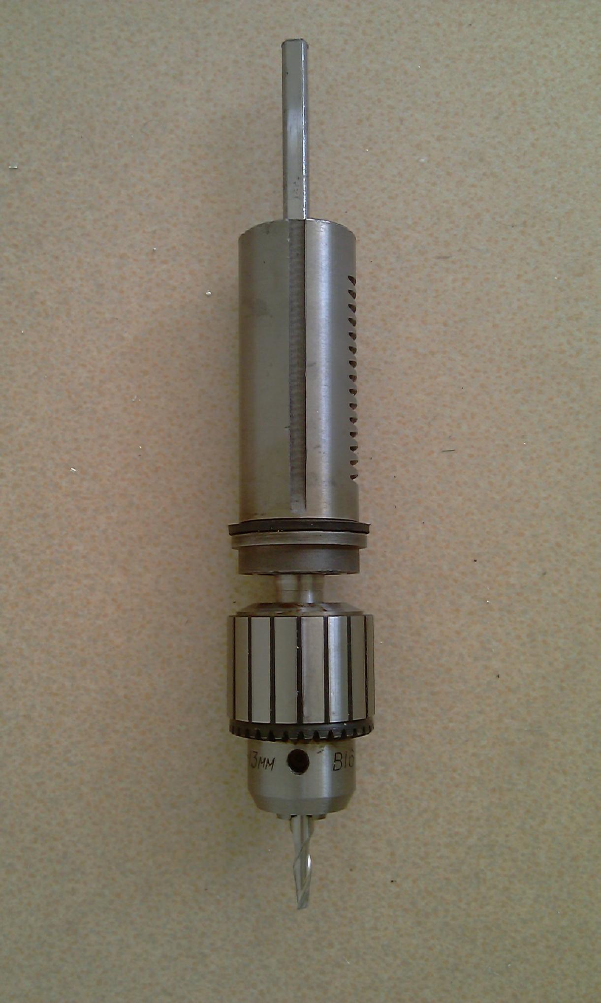
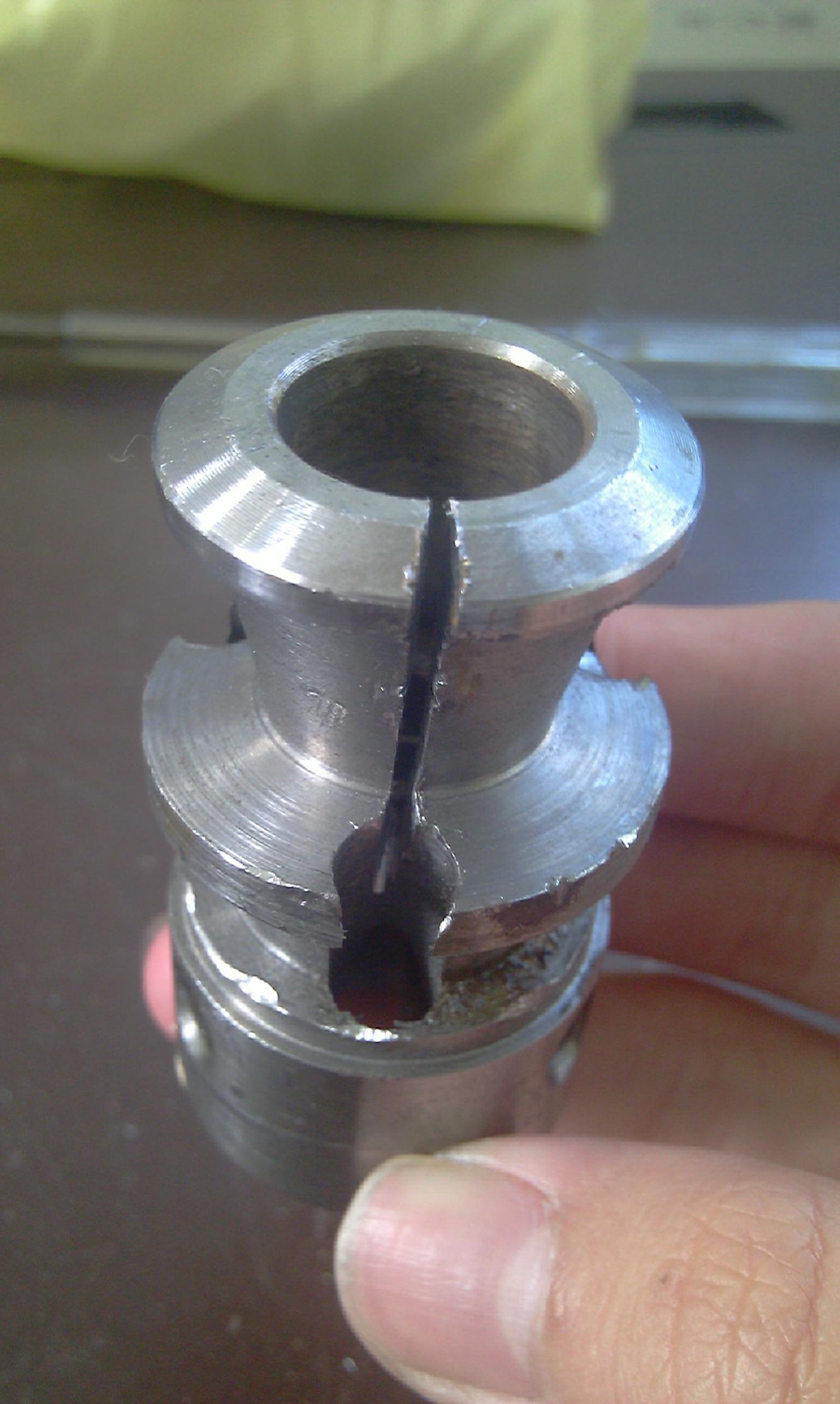
    I headed down to Chan Man Lee during lunch upon the advice of Wongster to get a new B16 drill chuck, I've attached a photo of it. It's of much more substantial construction than the previous one, being of solid steel construction. I'll check the runout tomorrow.
    Apparently the B16 taper is a German taper, having the same taper to length ratio as a morse taper, just shorter. Also, I forgot to add that it's a protruding arbour, and not a typical internal taper on normal mills.
    I think I will make do with the chuck instead of troubling others.
    Btw, the object in the first photo is the previous mutilated drill chuck <br> <br>

    Comment


      #47
      Nice... Did you take the opportunity to replace the bearing? That's the part that will give you the side loading problem.. Since it is already out, you can try stacking additional bearing on both side.

      Comment


        #48
        Good stuff. I read somewhere during my search that the tapers are not exact, as compared to the MT though close. The shorter length was my concern ("uneducated" one of course) when side load is applied.

        If you still want to explore making a adapter and endmills holder, let me know. It should be quite fun. Without time constraint, I can take my time to work on accuracy. Just for the fun of it, I'll put it in 3D to see if it looks right.

        Regards,
        Wong

        Comment


          #49
          Measured runout, it's 0.7mm, not as bad as the previous one, but still quite bad. Interesting thing i discovered when I checked the quality test sheet: it's 20 years old! <br> <br>

          Comment


            #50
            I used my drill press for milling a short time ago.
            These were my modifications:

            1. Shorten the cylindrical back column to lower the drill head so the quill do
            not have to be extended too far out.

            2. Used two screws to hold the quill in place. These had to be retighten
            every time a height adjustment was made.

            3. Drilled at the side of the chuck and installed grub screw to prevent
            the chuck flying off the spindle.

            I had smooth finishes but I was working on plastics.
            The drill is now back as a drill and I do not notice any runouts after it
            was abused for the "Immoral" purpose.


            73 - sawit

            Comment


              #51
              Hi Sawit,
              I did different mods, but for the same objectives. I ground away the protruding flange in the head casring to allow the column to pass through, and slitted the boss of the quill to allow it to clamp around the quill with a bolt passing through the head.

              When removing the y axis leadscrew to clear chips under the chip cover, I discovered that using one's hand to directly move the table was much more efficient for removing large amounts of stock. Each pass would take less than a second, compared to turning the leadscrew countless times for each pass. Somethig like rapid feeds on a cnc machine. The time taken to rough out chunks of metal is really far quicker.

              I'm currently milling standoffs for the y axis to extend the travel by about 2 inches; it allows the table to overhang.

              Comment


                #52
                Originally posted by F-WWOW View Post
                Measured runout, it's 0.7mm, not as bad as the previous one, but still quite bad. Interesting thing i discovered when I checked the quality test sheet: it's 20 years old!
                To minimise runout, you'll need endmill holders. drill chucks are not designed to take side load.

                Let me know the usual size of the endmill you're using. I'll see if I've some time over the weekend to make something for you to try.

                Comment


                  #53
                  Originally posted by F-WWOW View Post
                  Measured runout, it's 0.7mm, not as bad as the previous one, but still quite bad. Interesting thing i discovered when I checked the quality test sheet: it's 20 years old!
                  Did you test the runout of the spindle without the chuck on?

                  Comment


                    #54
                    Hi Wongster,
                    the runout of the spindle itself is 0.01mm.
                    Thnanks for the offer to help, but i've decided to put the mill in storage for now, and save up for a lathe(if i ever manage to), and focus on other things. I really can't do much without a lathe..

                    Comment


                      #55
                      You may want to check this out. Exactly want I had in mind though I've no confident of making the internal taper.

                      Comment


                        #56
                        Update

                        After a long break, I've finally found the time to upgrade my machine. I drilled and tapped a 1" thick aluminium plate to use as a "tooling plate" by bolting it to the table with 6 bolts. Although definately not as flat as the original table, it adds much needed rigidity to the table, which is actually made of thin extrusion. The drilling of the 21 holes took about 15 minutes, but the tapping took far longer; I only managed to tap 10 holes in about an hour(using a small pair of pliers)..
                        Up next should be a fine feed for the z axis using threaded rod.

                        Wongster: Thanks for the tip, I'll make do with what I have Click image for larger version

Name:	IMAG0398.jpg
Views:	1
Size:	393.6 KB
ID:	971425Click image for larger version

Name:	IMAG0399.jpg
Views:	1
Size:	389.8 KB
ID:	971426 <br> <br>

                        Comment


                          #57
                          Hi F-WWOW,

                          Well done. Keep up the spirit.

                          With the arrival of the Wabeco mill last Saturday, I'm considering selling the Sherline 5410 to free up some space for the other machines. The 2 Sherline mills are now standing very close together; too close to do any work with either one of them. But... I'm feeling a little reluctant to part with it... sigh...

                          Regards,
                          Wong

                          Comment


                            #58
                            Z axis Part 1

                            Here are the pics of the z axis block, which allows the z axis leadscrew (actually threaded rod) to thread through it. I used a m6 tap to tap through half of it, then drilled through the rest (the tap is too short). I'm not sure if I should add an anti backlash assembly, as I can't detect much slop at the moment.
                            The part which attaches to the quill is still not completed as I can't grind the tool bit to bore the 2" hole to the final size (my proxxon hand grinder switch died on me while i was grinding a stripped screw out of the drill press), so it'll have to wait. I have roughed out the hole by hand using the drill press and an endmill. Click image for larger version

Name:	IMAG0401.jpg
Views:	1
Size:	369.6 KB
ID:	971497Click image for larger version

Name:	IMAG0404.jpg
Views:	1
Size:	375.6 KB
ID:	971498
                            Now for a trip down to chinatown... <br> <br>

                            Comment

                            Working...
                            X