Announcement

Collapse
No announcement yet.

Canary - Trainer design for my school

Collapse

Zenm Tech Pte Ltd

Collapse

Visit Zenmtech at rc.zenmtech.com

X
 
  • Filter
  • Time
  • Show
Clear All
new posts

    #16
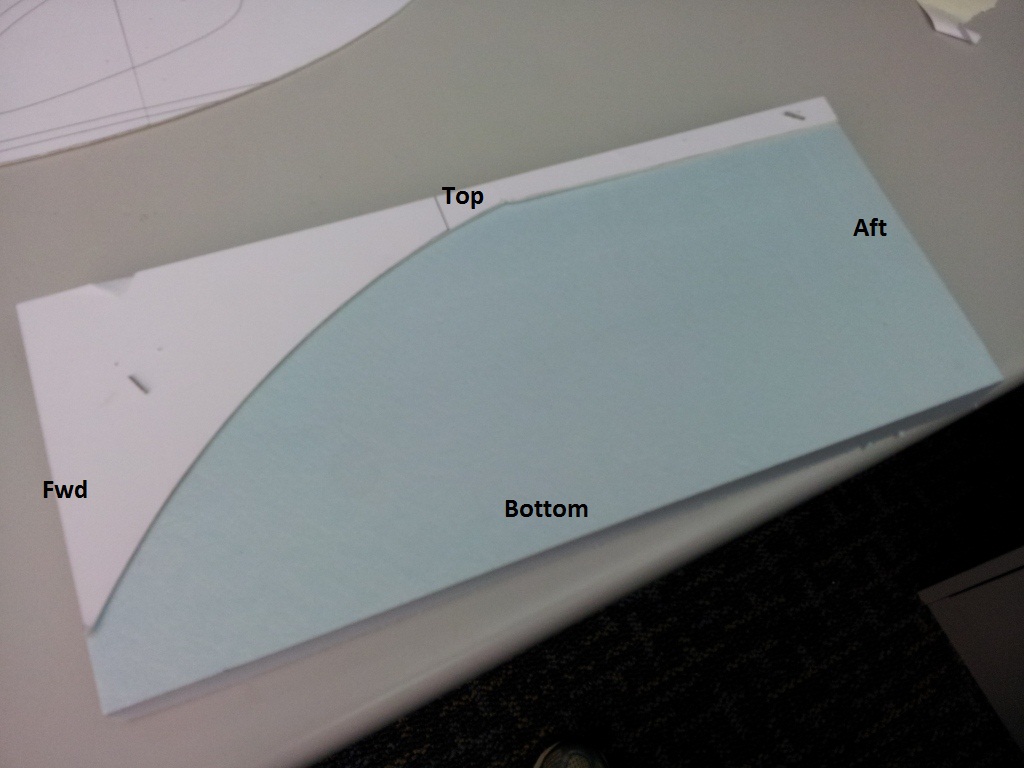
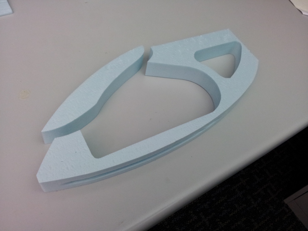
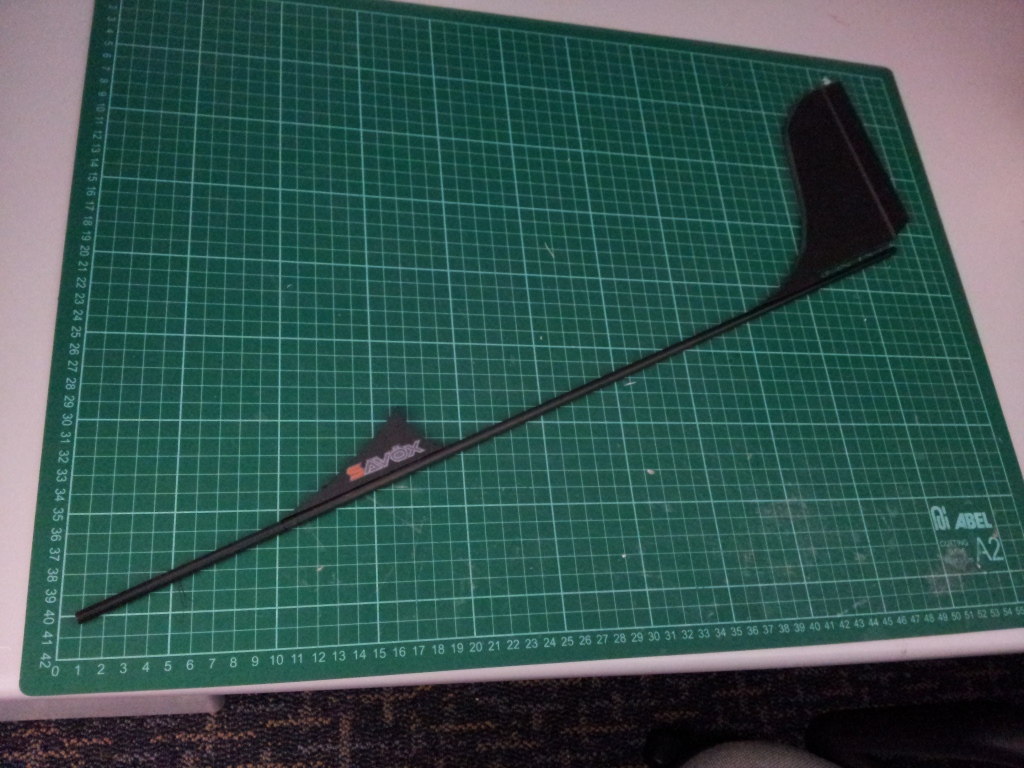
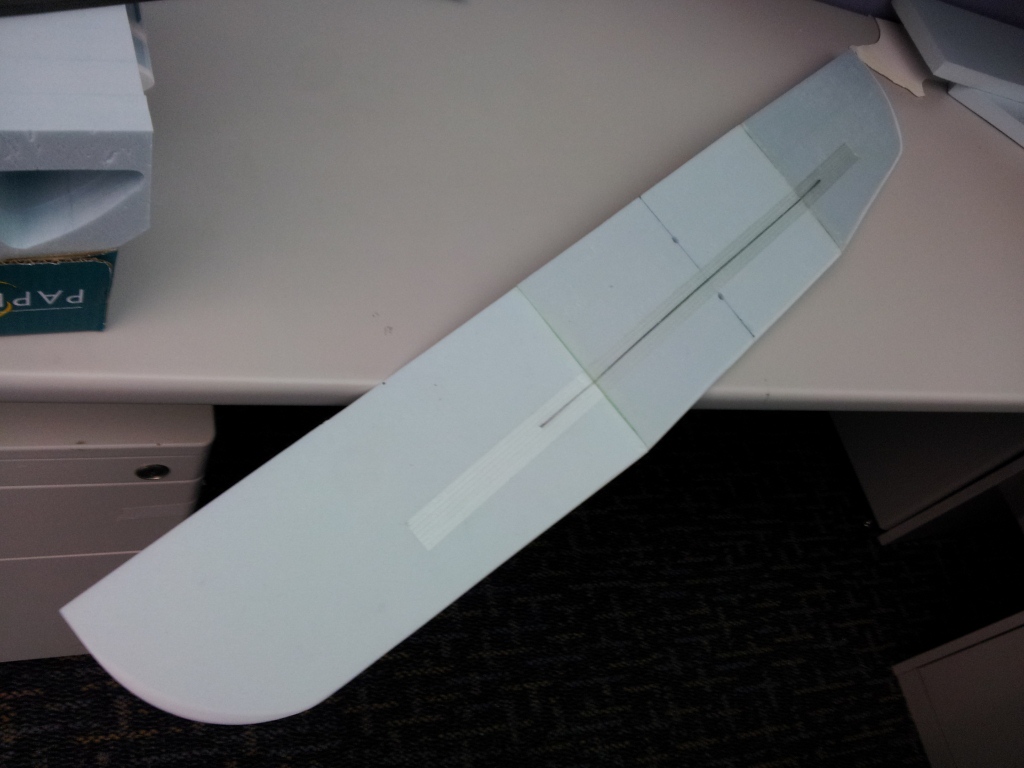
    The following pictures are taken from a scrap foam for illustration purpose, and as such, the tailboom access is absence in these pictures.

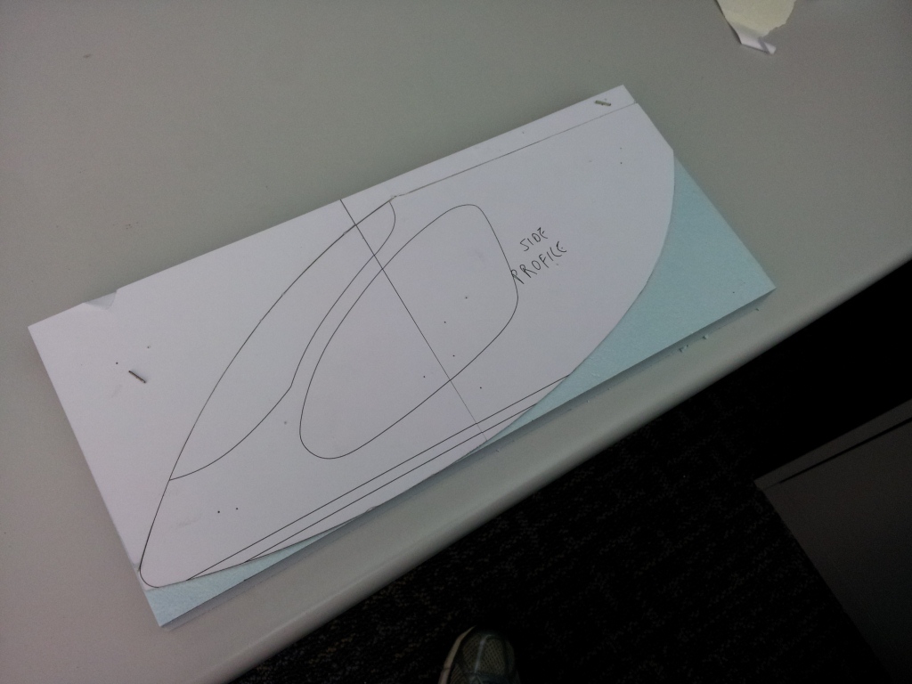
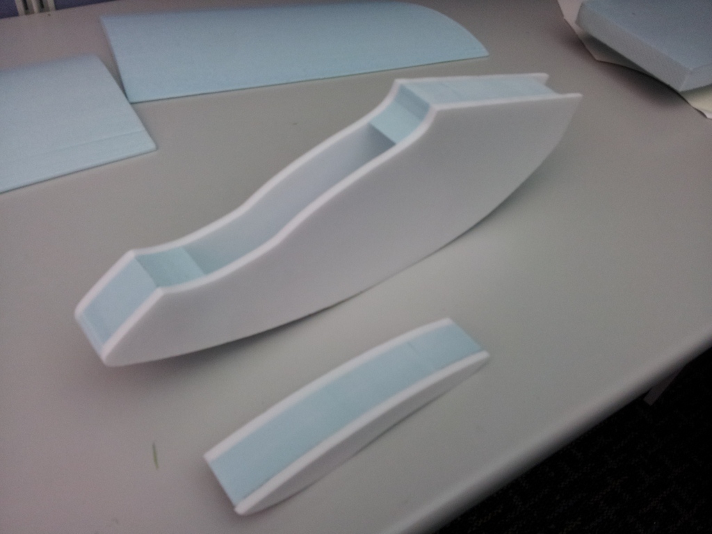
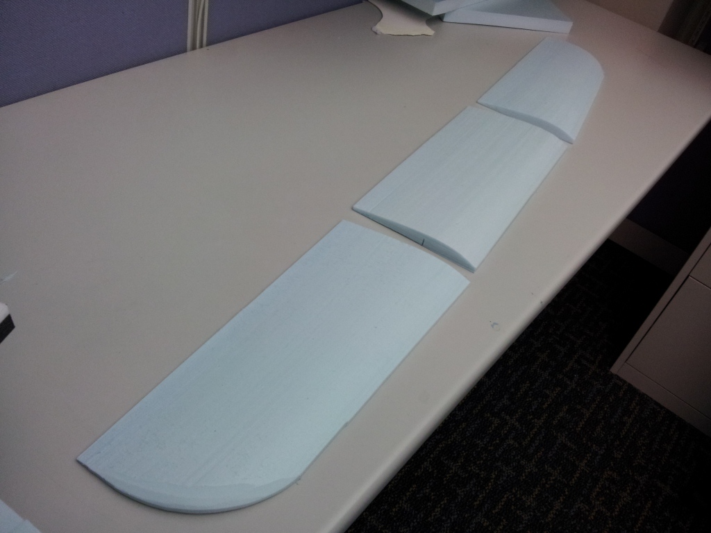
    Once the tailboom recess is done, pin the fuselage pod template jig on the upper edge of the block. It is not a template itself, but just a jig to pre-position the curvy shaped fuselage template. Next, place the fuselage pod side profile template against the jig, and either pin it onto the foam or use a light spray of 3M spray adhesive. Then, unpin and remove the jig.

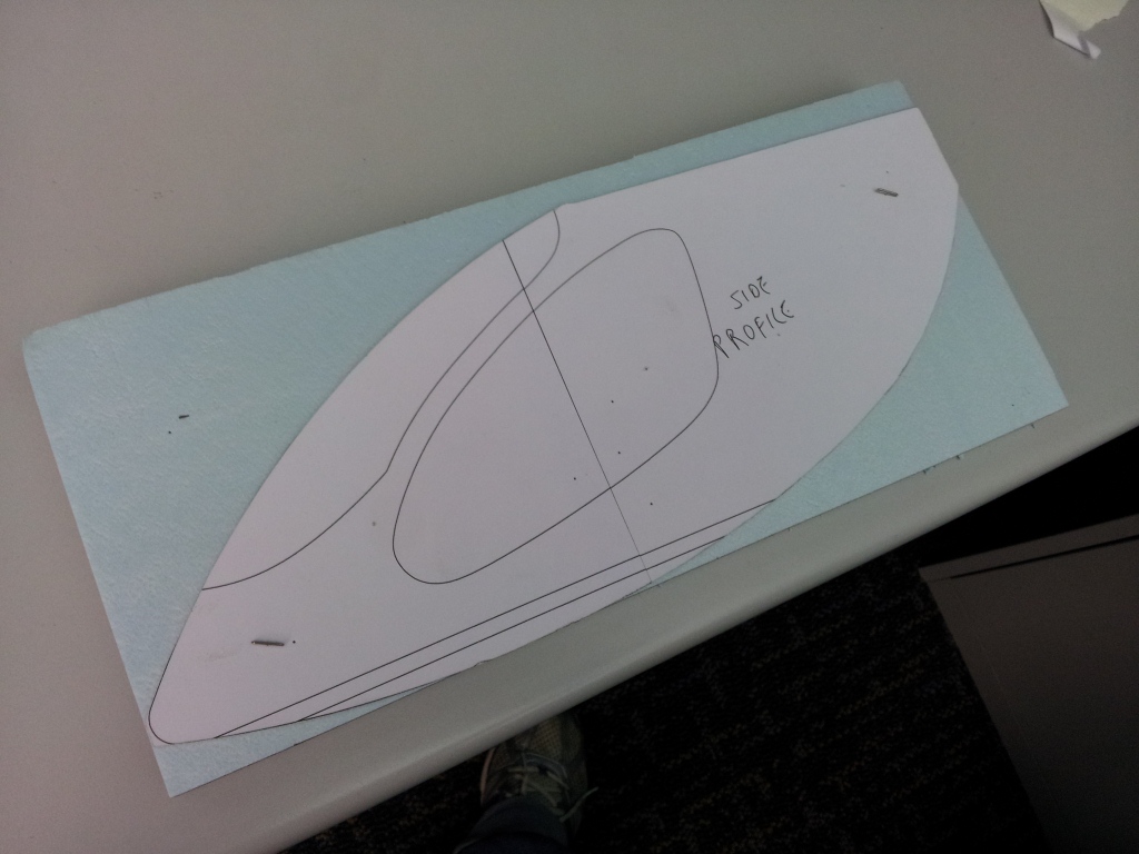
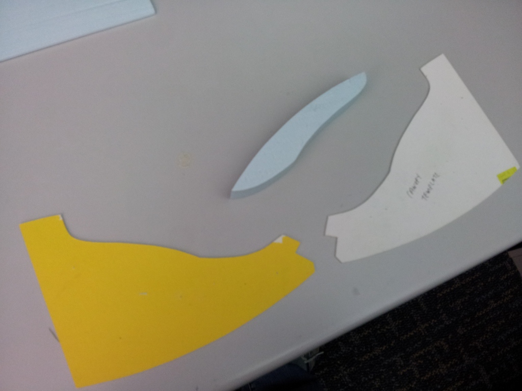
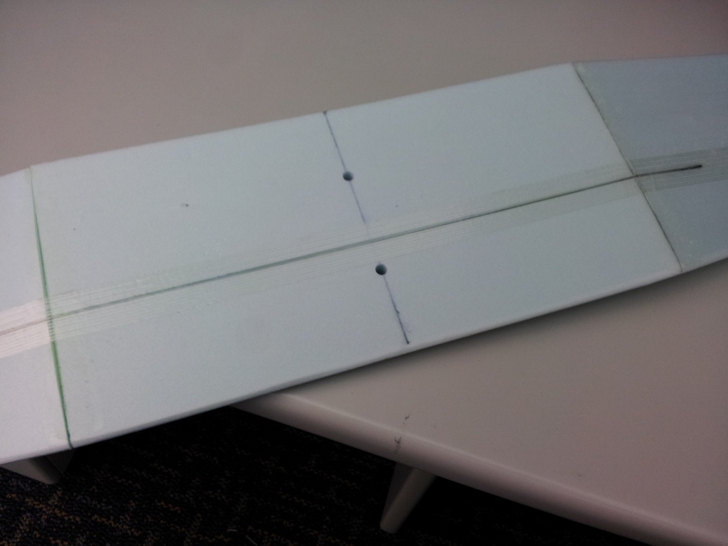
    Do the same on the opposite side of the foam block and make sure that both templates sits correctly and thier positions coincide with each other before hotwire cutting out the fuselage pod core.
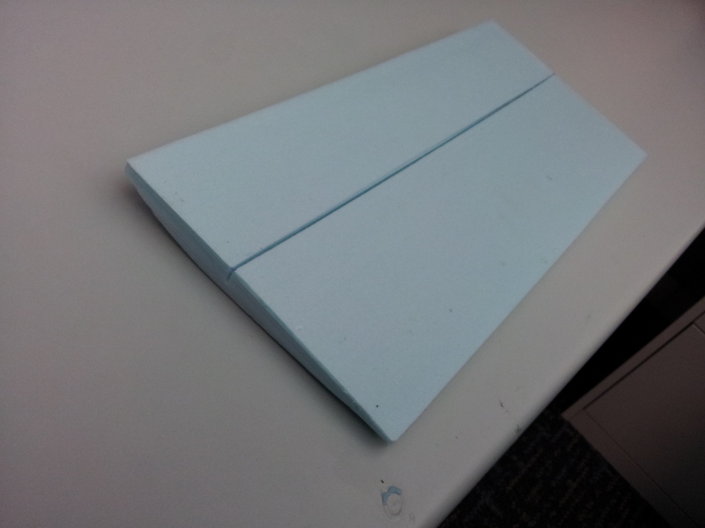
    Click image for larger version

Name:	20121105_131144.jpg
Views:	1
Size:	211.8 KB
ID:	972739Click image for larger version

Name:	20121105_131207.jpg
Views:	1
Size:	227.3 KB
ID:	972740Click image for larger version

Name:	20121105_131128.jpg
Views:	1
Size:	162.7 KB
ID:	972738

    Comment


      #17
      Using another 2 set of templates, hotwire cut out the canopy, and the internal cavities and lightening hole.

      If you are competent enough, you can stack a few pieces of foam sheets together with spray adhesive and hotwire cut a few fuselage cores at a time.

      Click image for larger version

Name:	20121105_131346.jpg
Views:	1
Size:	214.5 KB
ID:	972742Click image for larger version

Name:	20121105_131640.jpg
Views:	1
Size:	216.2 KB
ID:	972743Click image for larger version

Name:	20121105_131316.jpg
Views:	1
Size:	209.8 KB
ID:	972741

      Comment


        #18
        I forgot to take pictures of the fuselage pod side panels. Basically, they are cut from 6mm compressed foam sheets. I stacked up to 10 sheets of them with spray adhesive and hotwire cut all of them at one shot.

        The method is same to the fuselage core, except to stop right after the canopy is cut out.

        Following that, the side panels are glued onto the core with UHU-Por. Same for the canopy assembly.

        Click image for larger version

Name:	20121105_131600.jpg
Views:	1
Size:	200.4 KB
ID:	972744

        Comment


          #19
          At this stage, the fuselage pod assembly is sanded to its final shape and spray painted with foam-safe acrylic spray paints. I used contrasting colours for the canopy and windows, which the latter require masking.

          Click image for larger version

Name:	20121102_080711.jpg
Views:	1
Size:	363.5 KB
ID:	972745

          Comment


            #20
            Using a sharpened brass tube, cut a slot at the aft end of the fuselage pod, just below the motor mount area. The hole must cut through the core, all the way until it reaches the inner cavity below the canopy. This hole is for the ESC and its wires to pass through.

            Click image for larger version

Name:	20121105_140926.jpg
Views:	1
Size:	269.7 KB
ID:	972746

            Comment


              #21
              Next, cut the carbon rod to length epoxy the 6mm compressed foam vertical stabilzer assembly in place. The rudder is hinged with the fin with 3M Blenderm tape. Also, epoxy the support gusset onto the boom. You may need to buff the carbon tube's surface a little for the epoxy to glue well.

              The tailboom assembly is now epoxied onto the bottom recess on fuselage pod. Before glueing, you may need to sand and trim the recess for correct fit and alignments. Make sure that the fin is perfectly vertical at this point. Once the epoxy has cured, epoxy the taiplane assembly in place, making sure that it is perpendicular to the fin.

              Click image for larger version

Name:	20121102_085105.jpg
Views:	1
Size:	333.8 KB
ID:	972748Click image for larger version

Name:	20121102_085134.jpg
Views:	1
Size:	439.1 KB
ID:	972749Click image for larger version

Name:	20121102_080728.jpg
Views:	1
Size:	371.9 KB
ID:	972747

              Comment


                #22
                The wings wil be mounted by 2 plastic screws. You can use either nylon or acrylic screws around 6mm. The plastic/nylon nuts are epoxied into the foam, before being covered by a piece of fibreglass sheet epoxied onto the wing seat. Of course, the 2 holes are pre-drilled onto the fibreglass sheet beforehand to allow the screws to go through it.

                Click image for larger version

Name:	20121105_131948.jpg
Views:	1
Size:	226.5 KB
ID:	972750

                Comment


                  #23
                  The wings have flat bottom and the upper curvature is simply hotwire cut using a set of templates. The bottom of the centre wing panel has a slot hotwire-cut to receive the 4mmx1mm carbon spar. The outer panels have a 2.5" long slot cut at the bottom for the same reason, but by penknife instead.

                  The wing joints are hotwire cut or sanded to achieve 10 degrees of dihedral on each side before being joined together by epoxy.

                  Click image for larger version

Name:	20121105_131843.jpg
Views:	1
Size:	206.2 KB
ID:	972752Click image for larger version

Name:	20121105_131820.jpg
Views:	1
Size:	228.5 KB
ID:	972751

                  Comment


                    #24
                    Once the wing panels are epoxied together, the carbon spar is trimmed at the ends and epoxied across the wings, vertically. I also added a strip of fibreglass tape across. The wings will be very strong in this configuration. Marked out the centreline and the mounting screw positions before making the 2 holes with sharpened brass tube.

                    Click image for larger version

Name:	20121105_131907.jpg
Views:	1
Size:	214.2 KB
ID:	972753Click image for larger version

Name:	20121105_131921.jpg
Views:	1
Size:	202.2 KB
ID:	972754

                    Comment


                      #25
                      Nice !

                      Joe, have you ever thought of doing 3D Heli's canopy/Pod ?
                      The Canary's cabin reminds me of a flatten MS Protos canopy.
                      Seriously running out of ...Storage space !

                      Comment


                        #26
                        Nice.

                        Comment


                          #27
                          Originally posted by Ghostfit View Post
                          Nice !

                          Joe, have you ever thought of doing 3D Heli's canopy/Pod ?
                          The Canary's cabin reminds me of a flatten MS Protos canopy.
                          Actually, this is my source of inspiration. The Cavalon autogyro already has a pusher prop at the back, just change the tail and add wings!

                          Click image for larger version

Name:	cavalon-3.jpg
Views:	1
Size:	71.3 KB
ID:	972797

                          Comment


                            #28
                            =d

                            i finished mine but haven get the screw

                            Comment


                              #29
                              The flexible push-pull wire sheath is installed on the bottom of the fuselage by making 2 small holes with a needle file. I applied a few strips of tape to attach the sheath onto the tail boom.

                              Click image for larger version

Name:	20121105_132029.jpg
Views:	1
Size:	248.8 KB
ID:	972840

                              Comment


                                #30
                                With all structural jobs done, it's time to fix up the equipment. I started off by rigging and installing the rudder servo, followed by the elevator servo. Next, the motor is mounted onto a 1/8" plywood firewall, before being epoxied onto the fuselage pod, making sure that teh thrust line is at zero degrees.

                                The ESC is connected with the motor before being placed within the fuselage witha double-sided tape. Lastly, with all servo and ESC leads plugged into the receiver, it is placed under the canopy and secured in place with velcro tape. The 860mah 2S Lipo pack sits onto the nose.

                                Noticed from this picture? I've added a small tail skid to protect the elevator control horn from being damaged during landings.

                                Click image for larger version

Name:	20121102_085203.jpg
Views:	1
Size:	439.2 KB
ID:	972841

                                Last edited by joe yap; 09-11-2012, 04:23 PM. Reason: Additional info

                                Comment

                                Working...
                                X