Announcement

Collapse
No announcement yet.

Diy Lvd

Collapse

Zenm Tech Pte Ltd

Collapse

Visit Zenmtech at rc.zenmtech.com

X
 
  • Filter
  • Time
  • Show
Clear All
new posts

    Diy Lvd

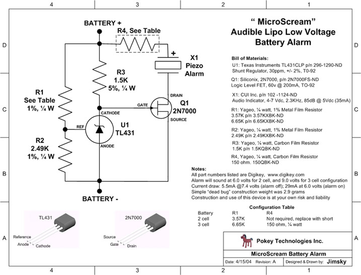
    Anyone tried to make this? http://www.rcgroups.com/forums/showthread.php?t=221018

    The parts may be bought from SLT level 3.

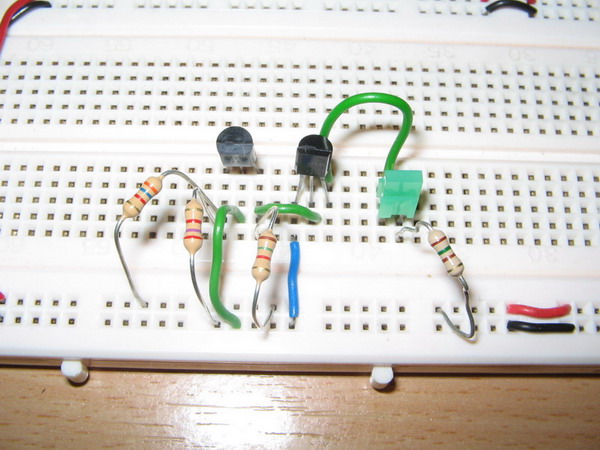
    Would appreciate it if someone who managed to get it to work share their experience. I pieced my on a breadboard but the thing doesn't work...

    Thanks!

    #2
    I didn't try but not sure others did or not.

    Why don't u post the pictures of your circuit (better quality abit) so we can troubleshoot it.

    Super-Hornet

    Comment


      #3
      Attached is the image. LED is wired in place of the piezo. If ckt is working, LED should no light when supply voltage is above cutoff since the FET is in the "off" state and current doesn't flow throught the LED.

      Supply voltage is fed through the bottom rail of the breadboard indicated by the red/black wire at the bottom right of photo.

      Would be great is anyone can help to debug based on this foto

      Many Thanks!

      Comment


        #4
        Replace 150ohm with a 330ohm resistor. I believe that you have already killed your LED in your earlier experience. There is nothing wrong with the connection.

        Comment


          #5
          Are u intend to design for 3Cell or 2Cell?

          By the look at R1 value, I assume u are building a 2Cell type. That means the voltage across the piezo will be 4 to 7Volt. With that, u need a resistor value that will not be too high for the LED and not too low for the LED. U choose 150Ohms... which is should be sufficient. Make sure your polarity of your LED is correct. If u think your polarity is correct, then try using lower Ohm value for the LED light.

          For Simple LED resistor calculator:


          Super-Hornet

          Comment


            #6
            Thanks for the input guys!

            Replace 150ohm with a 330ohm resistor. I believe that you have already killed your LED in your earlier experience. There is nothing wrong with the connection.
            Forgot to mention that the LED was "on" all the time... It should be On when Vsupply > 6V and Off when Vsupply < 6V.

            By the look at R1 value, I assume u are building a 2Cell type. That means the voltage across the piezo will be 4 to 7Volt. With that, u need a resistor value that will not be too high for the LED and not too low for the LED. U choose 150Ohms... which is should be sufficient. Make sure your polarity of your LED is correct. If u think your polarity is correct, then try using lower Ohm value for the LED light
            Yes I'm builting the LVD for 6V detect.

            Also, piezo refers to those flat discs right? ~50 cents one? And not the $2 type which the SLT ppl call "buzzer"?

            Btw, you guys seem to know the resistor color code by heart! have been messing with electronics circuits for a few years and i still need a table or DMM

            Comment


              #7
              Hi gEcky

              I think u have typo error is it? That circuit suppose to be buzz when voltage reaches 6V for 2Cell or when reaches 9V for 3Cell. When battery is full (That is 8.4V or 12.6V), it does not sound because the JFET is turn off. If you refering to your circuit always on even if it is at full cell, then something is wrong.

              Either your Q1 is wrong. Double confirm it. For what I know, JFET got P or N junction. The schematic I think is P Junction (If my memory serve me right). Other than that, could be U1 having problem?

              Can you measure voltage across:
              1 - Q1 Gate and Source
              2 - Voltage across U1 Ref and Anode.
              3 - Voltage acrosss R1.

              The Piezo use in this circuit is those Buzzer type. It is like those that got vibrator or vibrating soleniod inside. Not those flat button type. The Flat button type will not work in D.C. signal. (It need A.C. or oscillating signal to give u buzz)

              Super-Hornet

              Comment


                #8
                Hi Super-Hornet,

                think u have typo error is it? That circuit suppose to be buzz when voltage reaches 6V for 2Cell or when reaches 9V for 3Cell. When battery is full (That is 8.4V or 12.6V), it does not sound because the JFET is turn off. If you refering to your circuit always on even if it is at full cell, then something is wrong.
                paiseh, typo... Yup, it shd be "OFF when Vsupply > 6V and ON when Vsupply < 6V."
                Will do the voltage measurements when i get home. I suspect the TL431 i got is a bit dodgy and seems like i got the wrong type of buzzer.

                Comment


                  #9
                  After do some analysis on the circuit, the shunt regulator (TL431) was program to be 6.08V
                  The formula I think is:
                  Vout = (1 + R1/R2)Vref whereby the Vref = 2.5V

                  Therefore, for 2Cell,
                  Vout = (1 + 3.57k/2.49k)x2.5 = 6.084V

                  For 3Cell,
                  Vout = (1 + 6.65k/2.49k)x2.5 = 9.17V

                  So, your circuit should have 6.084V across Gate-Source of 2N7000.

                  Since the Vout is depend on your R1 and R2, u need to make sure you have accurate resistance value. If u get lower voltage across Gate-Source, u might need to connect a variable resistor in series with R1 so that u can manually tune it till u achieve 6.084V across Gate-Source.

                  If u achieve 6.084V or lower at Gate-Source, and u does make sure your Q1 is working, then u have to use higher resistance value for your LED.... If u intend to use LED. If using buzzer, even there is voltage flow through the buzzer (that is the JFET is turn on but partial on only), the buzzer will not sound untill it reaches 4V.

                  PDF on TL431:

                  or for more detail (53 pages)


                  Super-Hornet

                  Comment


                    #10
                    Hi,

                    i did the mesurements...

                    For 4v < Vsupply < 6v : Vref=2.5v Vout=2.5 (Led bright)
                    6v < Vsupply < 13v : Vref=2.5v Vout=1.8 (Led less bright)
                    Vsupply > 13v : Vref< 2.5v Vout=0.75 (Led turn off)

                    From above observation and FET datasheet, the FET needs Vgs > 0.8v (min) to turn on... thus LED lights when Vgs > 0.8 and only off when Vgs < 0.8 (when Vsupply is > 13v).

                    Seems like the TL431 is not behaving correctly? Btw, I got 4 TL431 and 4 FETs...all behave the same.... hmmm.....

                    Help? Anyone?

                    Comment


                      #11
                      Your Vout is reference from where? Voltage across LED or Voltage across Cathode and Anode?

                      I suspect your R1 and R2 resistance not correct... But first tell me what Vout are u refering to?

                      Super-Hornet

                      Comment


                        #12
                        Hi Super-Hornet,

                        my Vout refers to Cathode-Anode voltage. R1 and R2 values are correct... without the TL431 the potential divider formed gives 2.5v....

                        Thanks!

                        Comment


                          #13
                          Hi gEcky

                          Unless I read wrongly on the characteristic on TL431 or I did something wrong here... Here is what I understand.. Correct me if i'm wrong:

                          The TL431 is actually act like a programmable zener diode. It will clamp down the voltage (Just like zener diode) regardless of what is its i/p voltage. The o/p of the programmable zener is depend on what is your R1 and R2. Its breakdown voltage (or turn on voltage is at least 2.5V Volt or higher).

                          OK, suppose u supply 8.4V i/p to the whole circuit. And let say u do not connect the TL431. So, the R1 and R2 act as a voltage divider. Now according to Voltage Divider formular, the voltage across R2 will be
                          Vr2 = [R2/(R1 + R2)]Vin
                          Vr2 = 3.4515V

                          The TL431 has a Vref of 2.5V. Meaning it will turn on once the voltage across Ref-Anode is Greater or equal to 2.5V.

                          So, if u put in TL431, the TL431 will turn on because Vr2 > 2.5V. So, if u measure Vr2 without TL431 and and it is equal to 2.5V, then your R1 and R2 is wrong already lah.

                          Now since the TL431 is turn on, the Voltage across Cathode-Anode will be equal to Vout. This Vout will be depend on what is your R1 and R2 value because it is a programmable zener diode!
                          So, the formula is in the TL431 characteristic manual... That is
                          Vout = (1 + R1/R2)Vref whereby the Vref = 2.5V

                          Therefore,
                          Vout = (1 + 3.57k/2.49k)x2.5 = 6.084V.

                          Since Cathode-Anode is 6.084V, the voltage across R3 will be Vr3 = 8.4V - 6.084V = 2.316V

                          Now I have to go and check out JFET characteristic. If my memory serve me correctly, how FET turn on or off is not based on Vgs voltage only... not like transistor.

                          For the moment, U try to achieve the above voltage first. Try measure the resistance using Ohmmeter. U can use variable resister in replace with R1 in order to achieve Vr2 voltage.

                          Super-Hornet


                          Voltage Divider Formula:

                          Voltage Divider Calculator:

                          Comment


                            #14
                            I post the schematic here for easy reference.

                            Comment


                              #15
                              Hi,

                              OK, suppose u supply 8.4V i/p to the whole circuit. And let say u do not connect the TL431. So, the R1 and R2 act as a voltage divider. Now according to Voltage Divider formular, the voltage across R2 will be
                              I got Vr2 = 2.5v when Vsupply is 6v. Will get back with the rest of the measurements.

                              The FET in the case is used as a sw. Will on when Vgs > Vgs_treshold which is 0.8v (min), 2.1v (typ) and 3v (max). Hope i didn't rem this wrongly...

                              Comment

                              Working...
                              X