Announcement

Collapse
No announcement yet.

Building "The Supersonic Lobster"

Collapse

Zenm Tech Pte Ltd

Collapse

Visit Zenmtech at rc.zenmtech.com

X
 
  • Filter
  • Time
  • Show
Clear All
new posts

    Building "The Supersonic Lobster"

    Hello everyone,

    I could not resist and got myself a "Supersonic Lobster".

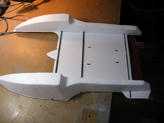
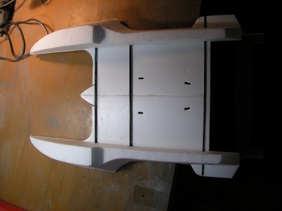
    A short description of the kit:

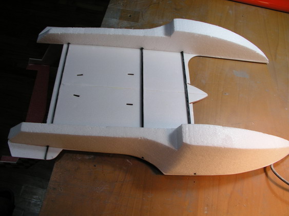
    - Printed and cut 3mm depron foam
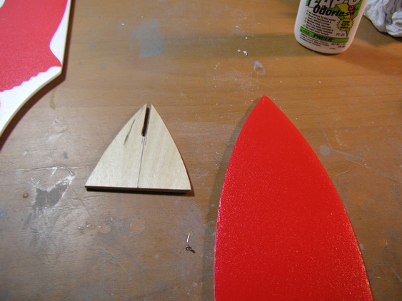
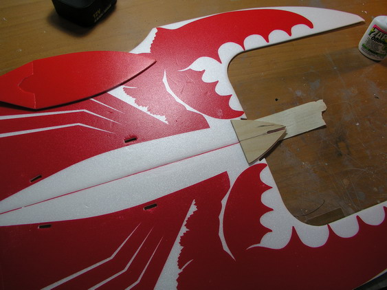
    - Ply wood dowels to strengthen the fuselage and rudder
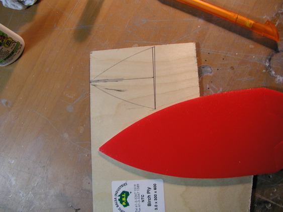
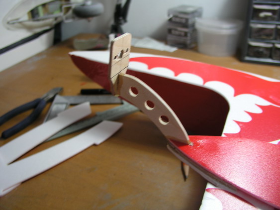
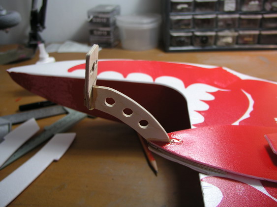
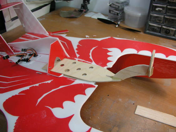
    - Plywood motor mount (not 100% sure how this works that's why I designed my own as you will see later)
    - Decals
    - Clear vac formed canopy
    - hinge tape
    - music wire pushrods
    - control horns

    What do you need to complete the kit:
    - Foam save CA
    - Uhu Por (I only used CA as I could not get the Uhu Por - was not the best choice)
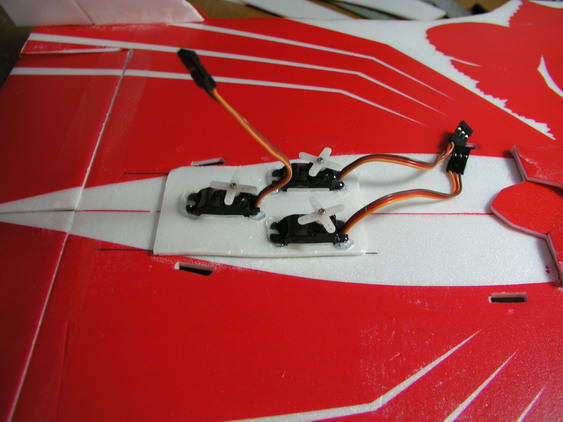
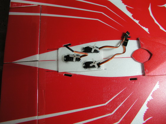
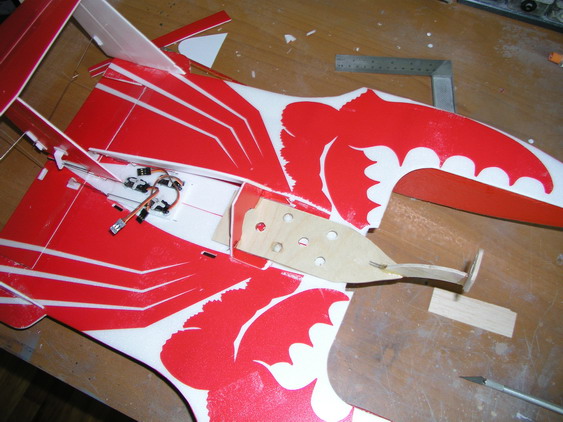
    - 3 servos (HS-55)
    - 4 channel receiver
    - Battery (I use a 3S1P 1200mA pack)
    - Radio with delta mixing
    - Brushless motor, esc and 8x4 prop
    - 30min Epoxy for the motor mount
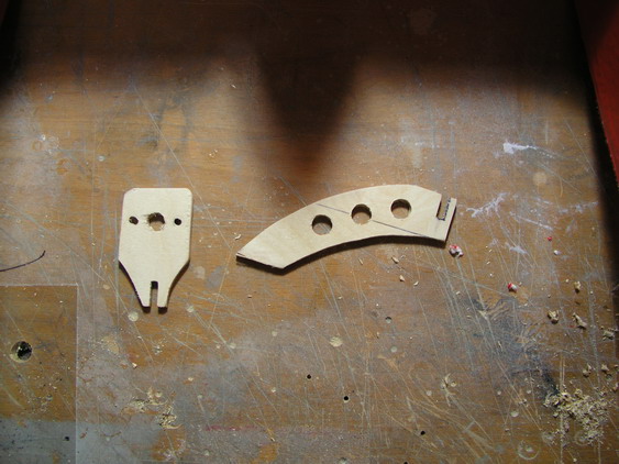
    - 3mm ply for the motor mount (only if you do your own mount design like I did)
    - 3mm Carbon rod (in case you do not want to use the supplied wood dowel)
    - 5mm hollow carbon tube (in case you do not want to use the supplied wood dowel)


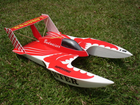
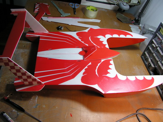
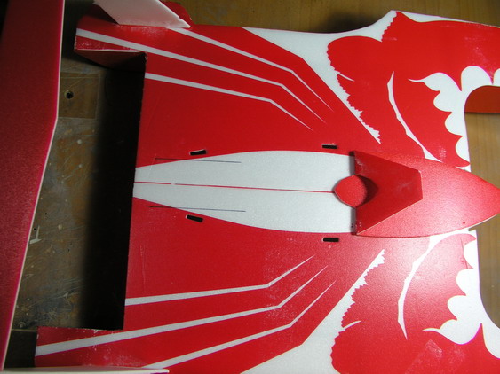
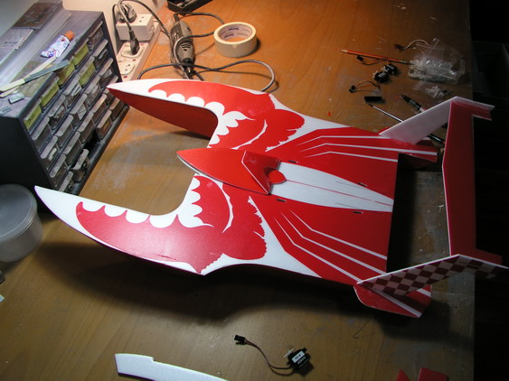
    This is how it should look like when finished:


    #2
    Unfortunately the kit came without a manual and as the manufacturer, after 3 weeks, has not been able to supply one I decided to go ahead and try my luck.

    This is what I did:

    Step 1:
    Align the two 1/2 fuselage parts and glue them together with uhu por or foam save CA.

    FIRST MISTAKE 
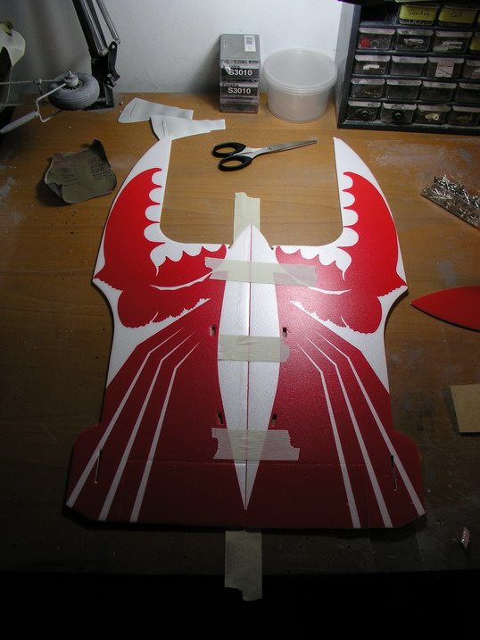
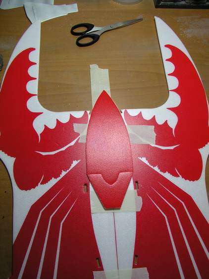
: Do NOT use masking tape. Yes it hold the parts nicely together but upon removal it will also strip your Lobster of some of his color

    Comment


      #3
      Step 2

      Step 2:

      Prepare motor mount.

      Picture 1: the kit comes with a pre-formed nose piece which is placed on the fuselage base plate in this picture.

      Picture 2: I used this part as template for my motor mount base plate

      Picture 3: 3mm ply wood base plate cut out

      Picture 4: motor mount base plate positioned and glued on top of the fuselage base

      Picture 5: Depron former glued on top = Motor mount Sandwich

      Comment


        #4
        Second Mistake

        SECOND MISTAKE:
        DANGER - DO NOT TRY THIS AT HOME:
        If, as shown in the pictures, the motor base plate is to short, the full force of the motor will be directed to the 3mm depron.
        This will result, in combination with a powerful motor and nice big airscrew, in a motor mount, esc and motor flying through the living room upon first taxi tests - go ahead and as ask how I know.

        The picture shows how it should be done instead.

        Comment


          #5
          Mmm.. That's is a nice seafood that you are building...
          Flying "lobster" huh.. well, I think i shall built a flying "prawn" or "Crab"
          to join you .. Haha..

          Comment


            #6
            LOL
            A very good idea. On the other side, a Lobster is also only a FAT prawn, right?

            Comment


              #7
              Step 3

              Step 3:

              I decided to use 2 carbon tubes (5mm - hollow) in front to strengthen the base plate and one 3mm carbon rod at the back.

              The 3 carbon rods are cut to size and reach from one edge of the base plate to the other.
              After they are glued to the bottom, slots are cut into the sponsons to allow a tight fit with the main deck.

              After that the sponsons are glued to the main deck (from the bottom of course ).

              Comment


                #8
                Step 4

                Step 4:

                i decided to cover the sponsons with red oracover to make them more durable and protect them for scratches/fraying during ground handling.

                I also mounted the rudder/elevator "bridge" at the rear end and marked the approximate location of the push rods for elevator control (the black lines).

                Comment


                  #9
                  Step 5

                  Step 5.

                  The location for the 3 servos are maked, reenforced with one additional depron plate and cut out.
                  Servos are fixed in place with hot glue.

                  Comment


                    #10
                    Step 6

                    Step 6:

                    The motor mount is VERY quickly cut out of 3mm ply and glued together (reason why they look a bit funny).

                    I did not drill the lightening holes in later versions (you need weight in the nose anyway).

                    Comment


                      #11
                      wah u really can.....building so many things at the same time..

                      nice lobster... ...i love seafood....
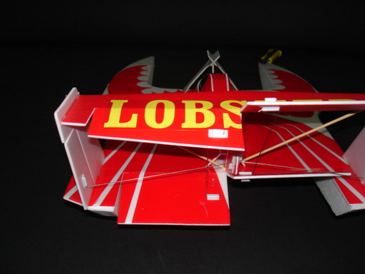
                      For Sale

                      CSM ICG400 Heading Lock Gyro+ ($160)
                      (

                      Comment


                        #12
                        MMMMmmm! me hungry too!

                        Comment


                          #13
                          Step 7

                          Before you start ordering Chili Lobster - quickly some more pictures

                          The middle rudder mount is glued between fuselage and top elevator bridge.

                          The moving parts of both elevator and rudder are fixed to the fuselage with clear packing tape (make sure they can move enough)

                          Next the control linkages:
                          Due to the delta configuration (left and right elevator are steered separately) a control horn has to be mounted at both lower elevators.

                          The left bottom elevator is then connected to the left top elevator, the right bottom elevator to the right top elevator and the middle rudder to the left and right rudders.
                          IMPORTANT You will have a lot of music wires going around from rudder to rudder and elevator to elevator, make sure they do not bind or touch each other during deflection.

                          All music wires get a V bend for easy adjusting later. The servo linkages are connected to rudder horn and servo with a Z bend.

                          Make sure everything can move freely and adjust the linkages (V bends) to center all elevators and all rudders.

                          Comment


                            #14
                            Hi Warbird

                            Any updates on how is your Chili Lobster hydrofoam flying?

                            Comment

                            Working...
                            X