Looking good man! 
|
| |
| a p l a c e RC&E HOBBYISTS m e e t | |
 hi DennisP many thank 4 ur advise but how much is the hot wire
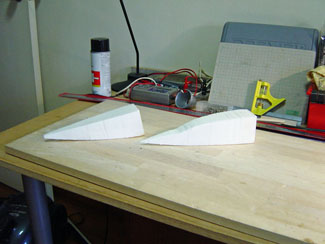
 Wow! Dennis, having this wire cutter doing the job is definitely much much faster than cutting individual pieces like i did, by Hand! Great!
  I smell a supersonic boom shockwave maiden in the month of June!
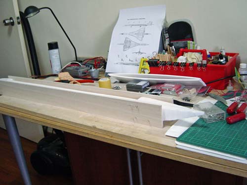
  , all will be revealed then.....
The Dremel adapator can be seen sitting behind the fin, it is used a lot in the USA and the UK to cut slots in plater board for power sockets and light switches.
, all will be revealed then.....
The Dremel adapator can be seen sitting behind the fin, it is used a lot in the USA and the UK to cut slots in plater board for power sockets and light switches.
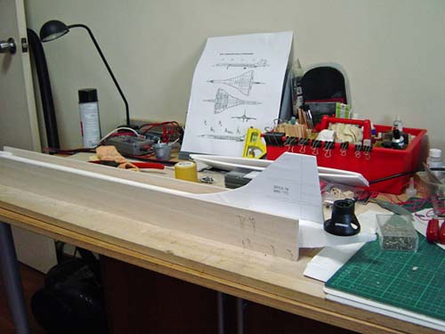 any idea what power system will be install in her Pushers or fan system?
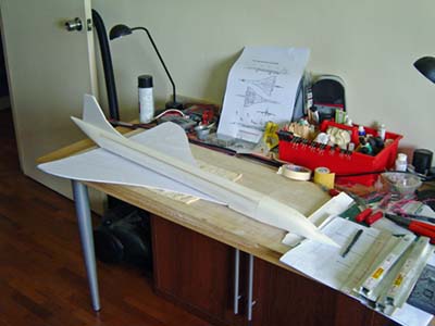 , carbon fiber stops the transmission of all RF signals, I did a test put the RX aerial in a CF tube and zilch no workie... So if the power wires to the pack were passed through a CF tube we should get no interference.? Now why am I doing all this silly stuff, well Concorde needs power to the two engine pods and also the servo leads from the engine pods need to run back to the fuselage, so if this works it will minimise the interference from the pods to the fuselage..? Like all things works well in the Lab but a different story in real life.
Comment