Announcement

Collapse
No announcement yet.

Royal SZD-26 Cobra-17 (2.6m)

Collapse

Zenm Tech Pte Ltd

Collapse

Visit Zenmtech at rc.zenmtech.com

X
 
  • Filter
  • Time
  • Show
Clear All
new posts

    Royal SZD-26 Cobra-17 (2.6m)

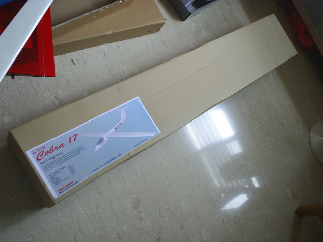
    I re-started this thread for my Cobra-17 for a good reason. This one would be a assembly log as a guide to others who wants or already has the kit. The previous thread was titled something else and I'd think that starting a new thread like this should be easier for the readers.

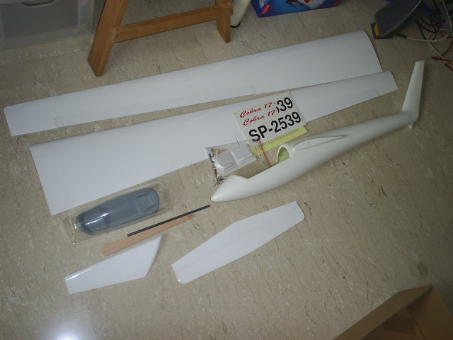
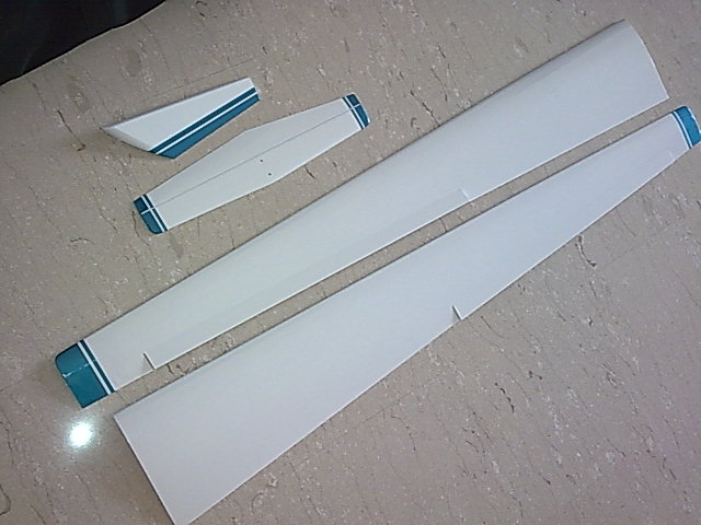
    Just a quick recap, this kit is solely distributed by Staufenbiel in Humburg at the moment and is manufactured in Czech republic by Royal-model. Fuselage is beautifully made of fibreglass, together with the canopy frame. The canopy is moulded from clear plastic. The wings, stabilizer and rudder are balsa built-up and covered in some kind of iron-on covering. Mine has a quite a bit of wrinkles and I have since redo the covering with Oracover. The kit comes with complete hardwares for the model. You'll need radio, battery, and adhesive to complete the model.

    The wingspan is 2.6metre, estimated AUW is 1.2 kg. Wing area is 34dm^2 and airfoil is S3010. 3 channel controls ( Ailerons, rudder and elevator) with 4 servos. You can program spoilerons if you wish to.


    #2
    I'm not sure whether I can make it, but I'm rushing to finish it before bringing it to Sedili this coming weekend.

    As said before, I do not quite like the coverings and I had since stripped them off and replace with Oracover more more durability, since I intedn to fly it at Sedili. Also, I added some colours to the otherwise, boring all white scheme.

    Comment


      #3
      Now, I'm really starting the assembly of this ARF proper.

      The first item is to do up the wing joiner system. It consists of a brass tube for the fuselage, a 1/8" diameter steel incidence pin and a 1/4" diameter steel joiner rod.

      The holes on the fuselage are not cut to the correct size and it needs some filings and trimming to get the brass tube in. The brass tube is also about 1/4" longer than the fuselage width and I cut the surplus off with a pipe cutter. I reamed the inner diameter to ensure smooth fitting with the steel joiner rod.

      Once aligned, I temporarily fitted the brass tube into the fuselage. The incident pin holes on the fuselage is a little too small for the pin to be inserted through. A small needle file is in the order of the day to loosen them up. Once done, I assembled the wings to the fuselage, but just to find out that the steel joiner is about 1/4" too long. However, the wing roots mate with the fairings perfectly. But that'll be tomorrow's job. Now I'm just too tired to carry on.

      Comment


        #4
        Next, I went on to install the elevator and rudder control bowden cable tubes. I temporarily taped them in place before putting blobs of epoxy to hold them down in place permanently. To minimise buckling, I added a balsa intermediate support in the vertical fin to the control cable tube. The rudder control tube exits at the left aft side of the fuselage and a small hole needs to be drilled to accomodate it.

        Comment


          #5
          Before gluing the balsa rudder post, I attach 2 screws onto it to serve as handles for positioning. The rudder post needs some trimming at the top to accomodate elevator control cable exit and the stabilizer hold down screw.

          I tacked the rudder post in place with CA before filling the gaps between it and the fin with epoxy/microballoon mix.

          The kit only provide 2 small hinges for the rudder which I find a little insufficient. I added an additional Du-bro hinge at the bottom to provide better support.

          I also kept the rudder control horn and its connection as simple as possible, instead of the hardwares provided. I found the last piece of fibreglass horn I bought earlier and epoxied it in place. I just use a simple Z-bend to connect it up with the control cable. The hinging is so smooth that the rudder always deflect downwards on its own weight.

          Comment


            #6
            I didn't take picture on this. I soldered the aileron servo wire extensions directly to the leads and run them through the pre-cut holes in the wings. After that, the servo lead connectors are soldered to the inboard ends of the extensions.

            Comment


              #7
              I thought of a simpler way to rig the aileron servos. Since the aileron servo bays have plenty of space, I do not want to pre-position the servos before rigging and use the space for adjustments later instead.

              To start off, I marked out the positions and epoxied the aileron control horns in place. Then, I centred the aileron servos with the radio energized and pre-set the servo horn positions. I always offset the servo horns slightly forward for sailplanes for differential throws.

              Next, I estimated the length of the control rod between the servo and control horns and bent a length of piano wire to suit. I made two off with the same length.

              This is where the actual rigging starts. I clamped the TE of the ailerons to the fixed TE of the wings to make sure that they are level. With the radio energized and control rods connected to the ailerons and thier respective servos, I epoxied the servo into thier wells.

              Let the epoxy cures, remove the clamps and voila! They are properly rigged without any further adjustments. Simple right?

              To make things easier further, I only Z-bent 1 end of each of the control rod, and made an L-bend on the other. The Z-bends are connected to the servo horns and the L-bends are only engaged to the control horns. When all riggings are done and the servo hatch installed, I just mixed a small batch of epoxy, wait till it turns a little gel like before forming a blob on the ends of the 'L' bends

              Comment


                #8
                The provided plywood elevator/rudder servo mount is meant for standard size servos instead of the HS-85MG I'm using. I decided to do it my old way. I cut 2 pieces of balsa sheets, carved one side round to suit the contour of the fuselage and epoxied them on each of the servos. Before that, the servos have one side sanded rough to improve adhesion.

                Then, I connected the servo horns to the push-pull cables, clamp down the rudder and elevator to thier neutral and epoxied the servos down onto the fuselage sides. This was done with the radio energized to ensure correct rigging.

                Comment


                  #9
                  Looks like this glider is heading for Sedili!!

                  Comment


                    #10
                    Next is the canopy. I taped the frame down firmly onto the fuselage with strips of fibreglass tapes. I only tape it on the sides of the frame. This is to facilitate removal later by pulling them off. Do not use other tapes as they may tear off later when you try to pull them out.

                    After cutting and trimming out the transparent canopy moulding, I ran a bead of Formula 560 canopy glue onto the frame, but not over the fibreglass tapes. When the glue turned a little not so watery, I placed the canopy over it and held it down with masking tapes and let it dry.

                    When the glue has dried, I peeled the fibreglass tapes free from the fuselage to remove the canopy assembly from it. Then, I pulled the tapes off the frame. It shuold not tear and should be able to be pulled out quite easily with a little force. The gaps they leaf behind were again filled with more canopy glue.

                    The end result is a good fitting canopy assembly.

                    By the way, the canopy frame is a little shorter than the cutout on the fuselage, but I placed it evenly within the cutout in my case. The clear plastic moulding is trimmed to fit exactly with the cutout, and by the end of the day, it extends a little beyond the frame. This is perfectly alright. After painting the frame, it will not be noticed. However, if you trim the canopy moulding accordling to the frame, you will get very big gaps between the assembly and the fuselage cutout.

                    Comment


                      #11
                      I attached the receiver and battery down with velcro, and installed about 3 oz of nose ballast to get the CG right. You'll need a pair of 6" long servo wire extension to connect the wing servos to the receiver.

                      AUW now is 1.32kg instead of the 1.2kg advertised. But I also realised that most manufacturers usually under rate the AUW. Although my canopy hold down system is still not in place yet, I thought of maiden it this afternoon at BR, while using tapes to hold it down.

                      Comment


                        #12
                        Originally posted by msc View Post
                        Looks like this glider is heading for Sedili!!
                        It is. But I don't know how am I going to fly it through the flock of gliders flying there this weekends.

                        Let me know if you got problem fixing yours up. BTW the steel wing joiner is not too long. It is too short and the problem that confused me is that a section of it has some inconsistant cross section, which impeded the insertion into the wings. I'd since filed and sanded it down until it fits nicely. However, I measured the depth of the wing joiner tubes and found that the steel joiner is about 1.5" short on each end. I'd since did some markings on it to ensure that it is inserted evenly on both wings. If you insert it fully in one wing, there'll be too little of the rod to support the other. Becareful!

                        Comment


                          #13
                          hi joe, you epoxied ur servos to the wing? What if the servo gear stripe and you need to replace the servo gear?

                          Multiplex Parkmaster 3D
                          Tarot 450SE V2

                          Comment


                            #14
                            Choose the best servos for the job and fly properly. I haven'y stripped a servo for a long time, other than during a crash. The servos will have to last as long as the model.

                            In the event that need a serv replacement, I guess I have to break the servo and clean the area up with a dremel. This is still better than losing a model to a loosely mounted servo.

                            Comment


                              #15
                              I normally wrap the servos with 2 layers of masking tape or u could use fiberglass tape. Be sure you wrap around the whole servos and not just the mating surface. I would apply epoxy on the masking tape and glue it to the wings. Should the servos need replacement or damage gears, cut the masking tape to remove the servos. Also remember masking tape over time detorate so after a some time inspect all the servos.

                              Comment

                              Working...
                              X