Announcement

Collapse
No announcement yet.

Most thrust on 65mm size EDF

Collapse

Zenm Tech Pte Ltd

Collapse

Visit Zenmtech at rc.zenmtech.com

X
 
  • Filter
  • Time
  • Show
Clear All
new posts

    Most thrust on 65mm size EDF

    Hi,

    In your opinion, what is the max thrust that can be achieved on a 65mm EDF? What is the brand of fan, motor and prop that will achieve that?

    How many max amps will this setup drain?

    Also, does anyone know what range of control signal that the ESC takes in to control 0-100% speed? I measured from a Futaba receiver and the signal output is 0.358V (0%) to 0.171V (full throttle).

    It is interesting the voltage range is so small - only 0.187V for 0~100% - , and that it works in reverse, i.e.: lower voltage represents full throttle. Did i get it right? I measured both channel 2 and 3 and they show similar result.

    Is the ESC flexible to take other voltage ranges for control signal other than from the receiver?

    The reason I ask is because I want to hook the ESC up to another signal not from the receiver...

    Any help appreciated. Thanks.

    #2
    What device did you use to measure the signal?

    Comment


      #3
      Originally posted by zxyong View Post
      What device did you use to measure the signal?
      I used a Fluke multimeter set to DC Volt measurement.

      I've also figured out that it does not matter that the voltage is lower at full throttle. On most transmitters that can be reversed for any channel. In fact, some brands of ESC ask users of Futaba radios to reverse the throttle channel before doing ESC setup.

      Comment


        #4
        Any advice on the best 65mm EDF that will give the most thrust?

        What about the fan's blades? I'm a newbie, so please advise on the blades to use. I read that more blades equals less efficiency in terms of watts used per kg of thrust. But my aim is most thrust, not worried about power.

        I.e.: I hear high speed blades really 'push' only when they are already travelling fast. But low speed blades give more acceleration from a low speed, such as during take off. Also, there is a difference between high speed fan blades and low speed fan blades?

        This means max thrust comes at different rpm levels for different kinds of blades?

        Comment


          #5
          Im not sure if you can measure the signal like this...

          For the propeller part, use a variable pitch propeller then! can even go backwards! (Theoretically)

          Comment


            #6
            Originally posted by robin silas View Post
            I used a Fluke multimeter set to DC Volt measurement.

            I've also figured out that it does not matter that the voltage is lower at full throttle. On most transmitters that can be reversed for any channel. In fact, some brands of ESC ask users of Futaba radios to reverse the throttle channel before doing ESC setup.
            You cannot use the DC fluke meter to measure the signal, the signal are digital pulses and are AC in nature.

            Most Fluke meter can measure both Ac and DC but
            the fluke meter Ac side is calibrated for rms ...meaning sinewave pulse only so are also unable to measure the signal meaningfully.

            Use an oscilloscope with sufficient badwidth to observe the signal.
            Anyway the signal are usually 3vp-p or 5v-p-p digital pulses depending on the design of the radio systems.

            cheers

            Comment


              #7
              Using an oscilloscope, you would find that the output waveform from the transmitter to the rx have been frequency modulated.

              Firstly, you'll have to understand the basics on how is the signal from your barethumbs from the sticks on the tx get transferred to the rx which controls the movement of the servos on the plane.

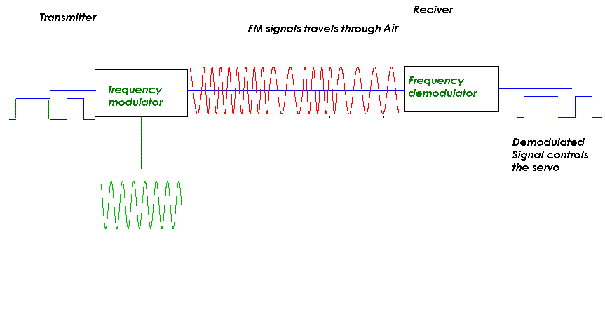
              see picture 1 and observe how is the digital signal from the tx get on the carrier frequency (which is your crystal frequency), transmitted through air and recieved by the RX onboard the plane.

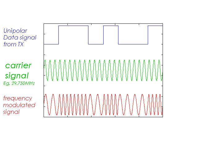
              picture 2 illustrate how FM modulation works, shows how the data signal modulated into an FM signal.

              Note when data input is high , FM frequency is higher
              Note when data input is low , FM frequency is lower

              *thus what babylon5 said was right, using a Multimeter will be impossible to see those waveforms , you'll need an oscilloscope

              Build it
              Fly it
              Crash it
              Fix it

              Comment


                #8
                Originally posted by robin silas View Post
                Any advice on the best 65mm EDF that will give the most thrust?

                What about the fan's blades? I'm a newbie, so please advise on the blades to use. I read that more blades equals less efficiency in terms of watts used per kg of thrust. But my aim is most thrust, not worried about power.

                I.e.: I hear high speed blades really 'push' only when they are already travelling fast. But low speed blades give more acceleration from a low speed, such as during take off. Also, there is a difference between high speed fan blades and low speed fan blades?

                This means max thrust comes at different rpm levels for different kinds of blades?

                What do you mean by most thrust? Static? Without variable pitch blades, you either get high pitch EDF (wemotec, HET, Shuebler) and get higher efflux velocity for achieve high speed applications (but suffer low static thrust and most likely need bungee launch) or lower pitch EDF (GWS etc) for higher static thrust and easier launch but suffer low speed ceiling.

                I have trouble comprehending this statement "read that more blades equals less efficiency in terms of watts used per kg of thrust. But my aim is most thrust, not worried about power"

                That is not true at all. Where did you read that? When you talk about power? What do you mean by that? Do unlimited climb or cover more distance for every watt used? You can achieve a 1.5 or even 2:1 power to weight ratio for a EDF plane and still not get it to fly well if your efflux velocity is too low. Similarly, there are people who achieve lower power to weight ratio 0.75:1 etc and still fly faster and more efficiently covering better range and flight envelope. For EDF, you would want more efflux velocity to carry through your flight moves and not power to weight ratio blindly.
                Stop looking for a gyro in my plane, they are all in the head.

                Comment


                  #9
                  Originally posted by viper1990 View Post
                  Using an oscilloscope, you would find that the output waveform from the transmitter to the rx have been frequency modulated.

                  Firstly, you'll have to understand the basics on how is the signal from your barethumbs from the sticks on the tx get transferred to the rx which controls the movement of the servos on the plane.

                  see picture 1 and observe how is the digital signal from the tx get on the carrier frequency (which is your crystal frequency), transmitted through air and recieved by the RX onboard the plane.

                  picture 2 illustrate how FM modulation works, shows how the data signal modulated into an FM signal.

                  Note when data input is high , FM frequency is higher
                  Note when data input is low , FM frequency is lower

                  *thus what babylon5 said was right, using a Multimeter will be impossible to see those waveforms , you'll need an oscilloscope
                  I think he was using it to measure the output signal pin of the RX or the 3rd pin of the RX.

                  But really, even if i managed to capture the radio freq, i wouldnt be able to make out what signal controls what.

                  Comment


                    #10
                    Originally posted by viper1990 View Post
                    Using an oscilloscope, you would find that the output waveform from the transmitter to the rx have been frequency modulated.

                    Firstly, you'll have to understand the basics on how is the signal from your barethumbs from the sticks on the tx get transferred to the rx which controls the movement of the servos on the plane.

                    see picture 1 and observe how is the digital signal from the tx get on the carrier frequency (which is your crystal frequency), transmitted through air and recieved by the RX onboard the plane.

                    picture 2 illustrate how FM modulation works, shows how the data signal modulated into an FM signal.

                    Note when data input is high , FM frequency is higher
                    Note when data input is low , FM frequency is lower

                    *thus what babylon5 said was right, using a Multimeter will be impossible to see those waveforms , you'll need an oscilloscope

                    Thanks for the comments Viper. Understood you, and FM is not the only tech the use now for covering the 'wireless' part, now there's PCM and spread spectrum transmission too.

                    That's all quite complex, but what I'm asking is the 'wired' signal part; i.e.: the signal output from the receiver to the ESC. What is the signal between the receiver and ESC.

                    Apologies if I was not clear before in asking

                    Comment


                      #11
                      Originally posted by edmond22 View Post
                      What do you mean by most thrust? Static? Without variable pitch blades, you either get high pitch EDF (wemotec, HET, Shuebler) and get higher efflux velocity for achieve high speed applications (but suffer low static thrust and most likely need bungee launch) or lower pitch EDF (GWS etc) for higher static thrust and easier launch but suffer low speed ceiling.

                      I have trouble comprehending this statement "read that more blades equals less efficiency in terms of watts used per kg of thrust. But my aim is most thrust, not worried about power"

                      That is not true at all. Where did you read that? When you talk about power? What do you mean by that? Do unlimited climb or cover more distance for every watt used? You can achieve a 1.5 or even 2:1 power to weight ratio for a EDF plane and still not get it to fly well if your efflux velocity is too low. Similarly, there are people who achieve lower power to weight ratio 0.75:1 etc and still fly faster and more efficiently covering better range and flight envelope. For EDF, you would want more efflux velocity to carry through your flight moves and not power to weight ratio blindly.
                      Refering to the blades and efficiency, i read that on a US forum. According to them, a two blade prop may generate less thrust, but will consume much less energy than say a 5 or 6 blade (which produces more thrust), even if the pitch and blade design were similar. Makes some sense as the blades have mass and it takes energy to spin them, so extra blades need extra energy.

                      Also, since they are arranged in a circle i.e.: 360 degrees being the limit, more blades means they are closely spaced, the 'next' blade will be trying to push 'disturbed' air of the previous blade, making it less efficient. If the blades are less, they are further apart and therefore will go through less 'disturbed' air and be more efficient.

                      Theoretically, it could mean two 3 blade fans arranged in a single duct will be more effiecient than one 6 blade fan. I can foresee this arrangement makes more torque, but as for thrust... hm...

                      All EDF I've seen so far are fixed pitch, pls show me a site which has variable pitch EDF if there is one.

                      I mean battery power when i said 'power'. I.e.: i'm not worried about flight time at all, and to clarify what I'm doing, it's because it is going to be a static installation EDF (not on a plane). So energy source should not be a worry.

                      What I'm trying to do is to modulate the speed of the EDF via an ESC so I need to know what the ESC responds to in terms of the control signal, which usually comes from the receiver, but in my case, I want to replace the receiver with another circuit that mimics or gives similar signal as the 'wired' output from the receiver to the ESC.

                      Since this part is a wired part and the receiver functions on battery power (i.e.: DC voltage) i do not think that they would covert it to AC again (which would require additional electronics components) to control servos or ESC.

                      Comment


                        #12
                        Originally posted by robin silas View Post
                        Thanks for the comments Viper. Understood you, and FM is not the only tech the use now for covering the 'wireless' part, now there's PCM and spread spectrum transmission too.

                        That's all quite complex, but what I'm asking is the 'wired' signal part; i.e.: the signal output from the receiver to the ESC. What is the signal between the receiver and ESC.

                        Apologies if I was not clear before in asking
                        As far as i know its a digital pulse. the time between the pulses determines the servo position. 1.5ms = servo centre

                        Comment


                          #13
                          Checked and it's actually the duration of the pulse that determines the servo position ...oops i got it wrong

                          Comment


                            #14
                            found this ...hope it helps >>>>

                            Servo Control Basics
                            The servo signal is a simple digital pulse. It spends most of its time at a logic low (0 V). About every 20mS it goes logic high (3 to 6 VDC) and then quickly goes low again. It is this tiny window of logic high time, called the pulse width, that gets the attention of the servo.

                            Please refer to the drawing. The period labeled "A" is called the frame rate. In the example it is repeated every 20mS (50 times per second), which is quite typical for most radio systems.

                            Modern servos define center as a 1.5mS pulse width, as shown by detail "B" in the drawing. Full servo rotation to one side would require that this pulse width be reduced to 1.0mS. Full rotation to the other side would require the pulse width to increase to 2.0mS. Any pulse width value between 1.0mS and 2.0mS creates a proportional servo wheel position within the two extremes. The frame rate does not need to change and is usually kept constant.

                            The servo will not move to its final destination with just one pulse. The servo amp designers had brilliantly considered that multiple pulses should be used to complete the journey. This little trick reduces servo motor current draw and it helps minimize erratic behavior when an occasional corrupt signal is received. To move the servo, you must repeat the pulse every few milliseconds, at the chosen frame rate. Modern R/C systems use a 40Hz - 60Hz frame rate, but the exact timing is not critical. If your frame rate is too slow, your servo's movement will become rough. If the rate is too fast the servo may become very confused.


                            Comment


                              #15
                              Originally posted by robin silas View Post
                              All EDF I've seen so far are fixed pitch, pls show me a site which has variable pitch EDF if there is one.
                              I can't. That is what I said, without.

                              Originally posted by robin silas View Post
                              Refering to the blades and efficiency, i read that on a US forum. According to them, a two blade prop may generate less thrust, but will consume much less energy than say a 5 or 6 blade (which produces more thrust), even if the pitch and blade design were similar. Makes some sense as the blades have mass and it takes energy to spin them, so extra blades need extra energy.

                              Also, since they are arranged in a circle i.e.: 360 degrees being the limit, more blades means they are closely spaced, the 'next' blade will be trying to push 'disturbed' air of the previous blade, making it less efficient. If the blades are less, they are further apart and therefore will go through less 'disturbed' air and be more efficient.

                              Theoretically, it could mean two 3 blade fans arranged in a single duct will be more effiecient than one 6 blade fan. I can foresee this arrangement makes more torque, but as for thrust... hm...
                              How do you come that conclusion of the closer blades means disturbed air meaning less efficiency logic? If anything at all, you should take a look at how Jet engine compressor moves air and compress them, I would think they are very closely spaced and efficient at drawing air, hey they are so good at drawing that they actually compresses them. Efficient in drawing air? Efficient at producing thrust? The torque part confuse me really, can you explain more?

                              If anything at all, the reason for 4 blade 6 blades or whatever number is more to the designer trying to put out a EDF that can be sold and mated to as many motors commercially available as possible. There is a diameter constraint and this is why they go more blade to load the motor suitably to settle at high rpm but WITHIN spec. I am beginning to believe too many people are reading too much into the 2blades vs 6blades difference lol.

                              Ever met the guy that comes round and offered the reason why Vought F4U Corsair has gull wing like design for additional aerodynamic advantage when it is actually just to allow the plane to have bigger prop, retractable wings and shorter landing gears?
                              Stop looking for a gyro in my plane, they are all in the head.

                              Comment

                              Working...
                              X