I'm not sure this question has been asked before or not,anyway here goes.
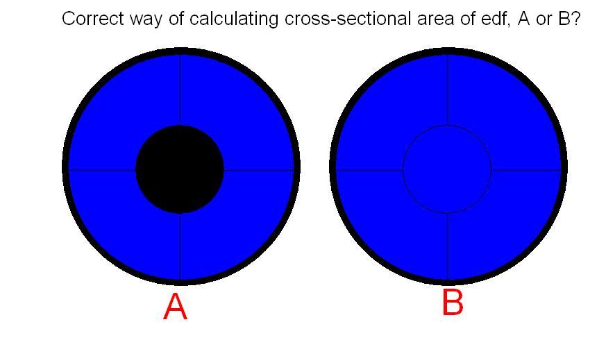
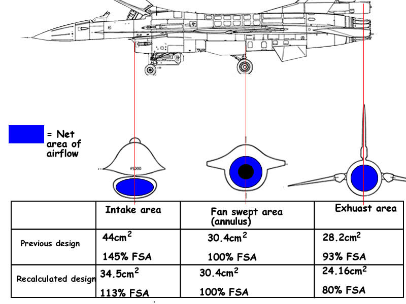
In order for me to predetermine my intake area and exhuast area, first i have to calculate my area of the edf, which is the net area of the air sucking through the fanblades.
So according to the diagram i drawn, which is the correct way of calculating the cross-sectional area of the edf (shaded in blue).
And it is best that the intake area is 100% or equal to the calculated cross-sectional area of the edf?
If too small, the edf will suck less and thus less thrust.
If too big, the extra area in the edf will creat unwanted drag.
Oh one more thing, i'm going to put a intake ring on my edf,even though it's going to be buried inside a ducting tube. I've done test and seems that it produce extra ~20% thrust with the intake ring.
Hope someone could anwser this so i could start on my next edf plane

 and 14lb thrust, thats like the weight of a bowling ball.


Comment