Announcement

Collapse
No announcement yet.

Need some help to cut some heli parts.

Collapse

Zenm Tech Pte Ltd

Collapse

Visit Zenmtech at rc.zenmtech.com

X
 
  • Filter
  • Time
  • Show
Clear All
new posts

    Need some help to cut some heli parts.

    Need some help to machine two parts for a heli. Material preferably in t7075 aluminium, but if its a lot more ex than 6061 aluminium, I might settle for 6061. So it price pending. Maker will help to supply material.
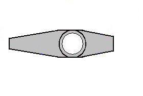
    1 piece of this

    45mm long and 12mm in diameter and the flat surface(two sides) has to be grind down to about about 10.9-11mm. 3hole(threaded) to suit a 2.5mm screw on each flat side, a total of 6 holes. A hole(none threaded) of 3.5mm has to go through from end to end with a 7.99mm diameter 4mm thick recess at both end to fit in a bearing each end. <br> <br>
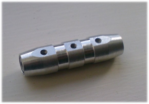
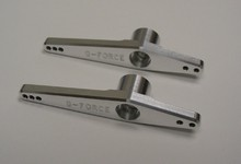
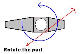
    sigpic

    #2
    and 2 pieces of this.

    about 50mm long and the bearing holder area is approximately 10mm thick. A total of 4holes(threaded to 2mm) to be drilled on each arm. One hole(7mm diameter 2.5mm thickness, non threaded) on each side of the arm to hold a bearing each side, meaing a total of 2 7mmx2.5mm holes each arm.


    Of course, I will give you all the dimensions before cutting, including hole spacing etc, but tentatively, those are all the holes that are required.

    You will only have to provide the material to cut out the 3 items(the round thingy in first post and 2 arms). I will source for my own bearings and screws and of course, I will pass you the bearings and screws to look look see see and measure, so that they will be no guessing or miscom.

    I understand this might not be a super duper easy task, so let me know how much it will cost. Thanks for reading. <br> <br>

    sigpic

    Comment


      #3
      BTW can contact me @96301398 if you can get it done. Thanks.

      sigpic

      Comment


        #4
        Hi, do you have a dateline for these items to be machine?

        Item 2 required cnc to cut it shape. Otherwise if done manually, it may not look nice.

        Comment


          #5
          bump. Still need help...

          sigpic

          Comment


            #6
            How to cut item 2 without cnc?

            If it just a triangle shape, still can file after manual cut, but the round extrude..I got no idea?

            Machinist can help?? I'm learning too.

            Comment


              #7
              item2 is harder to make than item 1? Paiseh, I have zero knowledge of machining.

              Then anyone capable and willing to help me machine just the first part? If anyone can...pls pm me to discuss about the price. Thanks.

              sigpic

              Comment


                #8
                Originally posted by rottweiler
                How to cut item 2 without cnc?

                If it just a triangle shape, still can file after manual cut, but the round extrude..I got no idea?

                Machinist can help?? I'm learning too.
                actually still can do manually for both, not as nice, more sq look, less work, more round more work, but can be done.

                i come out with an idea,
                you just need to play with the way you mount your parts.
                example, item 2, general shape on a mill

                1. remove as much unwanted material as possible, until a T shape block.
                2. drill the thur hole, this will be used as 1 point to secure the parts.
                3. remount to do a straight cut, then repeat 4 time for the general look.
                4. using the hole as mounting reference, turn you part and cut to get the
                circle look, the more time, the more round.
                5. do the same for the edge, will not be as round due to the radius reference to the hole.
                6. complete it with a hand file.

                below pics are for easy understanding, not to scale of course as using ms-paint. <br> <br>

                Its a Great day, lets fly, crawl, and fight.

                XRB SR Lama
                Robotis Bioloid
                Robot Bear

                <a href="http://asherong.sg">http://asherong.sg</a>

                Comment


                  #9
                  All the cuts looks straight forward except the round part. I wonder whether a round table will be able to help? If not will be lots of filing work.

                  Comment


                    #10
                    to be honest, it is not going to be an easy job, even with CNC. THis is because bearings needs to be fitted into that hole, and this requires a lot precision to ensure a snug fit. If you use pocketing, or normal drilling, you will not get a snug fit. It will be either too big or too small. The best method is to use a boring tool, which is a lot of manual labour. Other than that, the contouring of the other sides are not difficult.

                    If you wish, you can send me all your dimensions, i'll see if i can draw it out on solidworks. But i'm in HK now, i cannot machine it for you, but many somebody else can.

                    Comment


                      #11
                      Will it be possible to machine item 2 in 2 parts. The round extrude on the lathe and the "base" on the mill? Both parts press fit together and screw in?

                      Comment


                        #12
                        Originally posted by rottweiler
                        Will it be possible to machine item 2 in 2 parts. The round extrude on the lathe and the "base" on the mill? Both parts press fit together and screw in?
                        hmmm... not very possible as this is a lever and strength is required especially at the joint. Machining the entire part can be done w cnc.

                        I will machine every area and left the last part which the bearing suppose to sit. Thereafter, run a separate program and machine the hole in 0.01mm increment. Test fit bearing after each run.

                        In industrial, they are able to control the tolerance down to 0.01mm accurately, so they need not trial fit the bearing for every part fabricated

                        Mike

                        Comment


                          #13
                          From all the discussion, it seems that making these parts is going to be super duper complicated and extremely expensive(hundreds of moolah for the 3pieces??)...so I guess I will do away with the idea.

                          In case anyone is wondering/interested, the two items are flybar carrier and mixing level arm for the raptor 30/50/550/620 which will change the stock flyar ratio of the raptor. The stock flybar ratio of a raptor is 1:1, while the "modern" heli either have adjustable or somewhere around 0.8:1. With the kasama/G-force mixing arms that we commonly use on raptors to increase pitch range, the flybar ratio goes above 1:1. Colin Bell modify his flybar carrier by drilling another hole with 1mm spacing between the original hole and then using the R90 washout arm as the mixing level arm, which results in an overal flybar ratio of 0.85 and increased possible pitch range of +/-15. How much difference does the flybar ratio makes? I honestly don't know, which is why I want to try...

                          sigpic

                          Comment


                            #14
                            there is a mod on another forum where people use the 60/90 mixing arms and make some modification to it to increase the pitch.

                            Comment


                              #15
                              Yup, thats the northenlight(If I remember correctly) mod. W/O redrilling the flybar carrier, the flybar ratio will be slight increased from the stock 1:1. Cbell took it one step furthur by redrilling the flybar carrier to drop the flybar ratio to 0.85.

                              sigpic

                              Comment

                              Working...
                              X