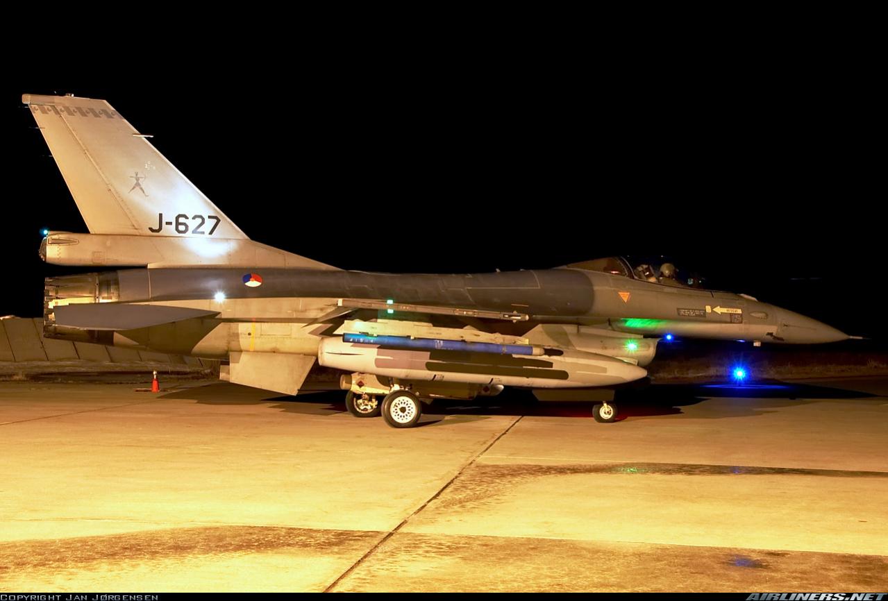
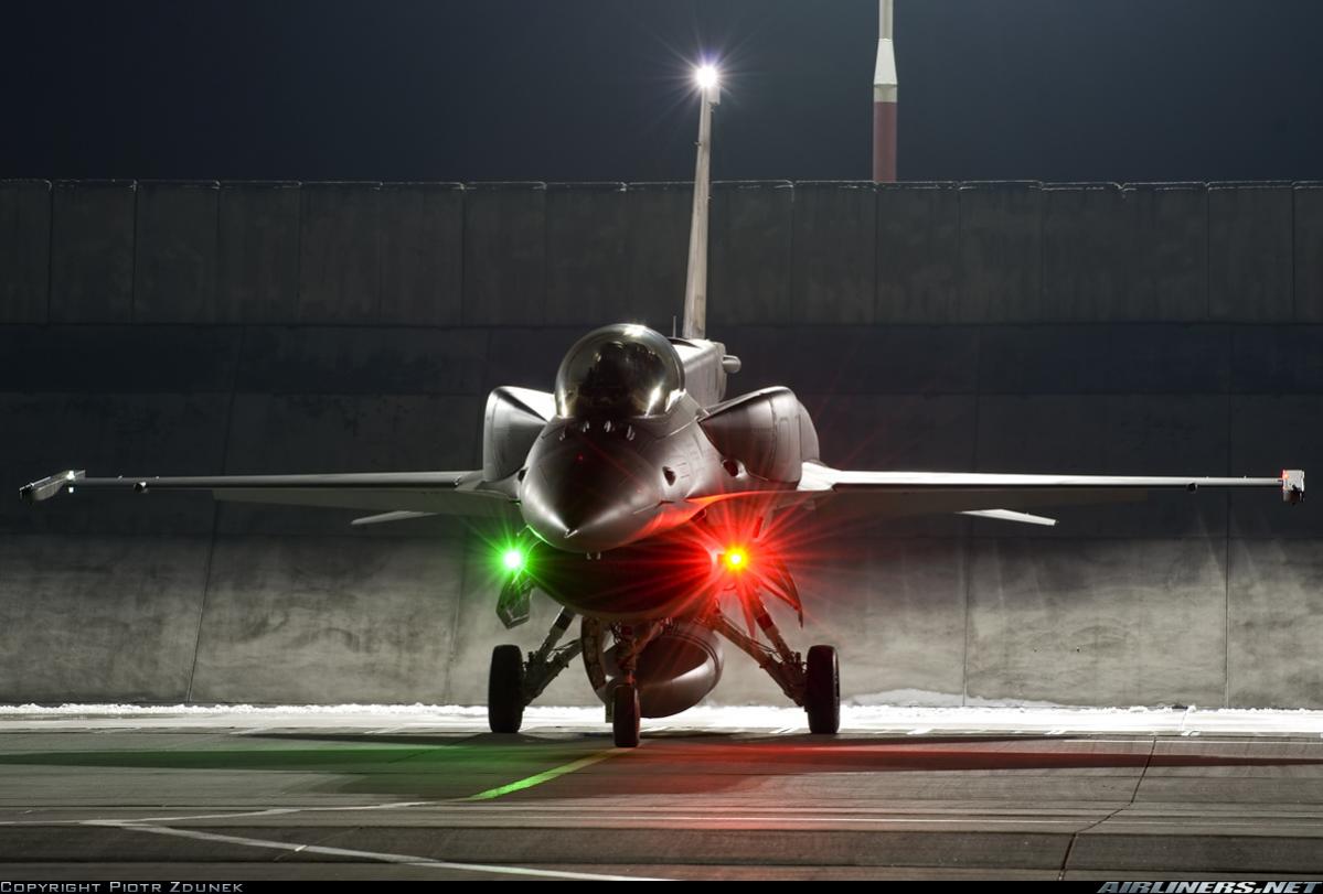
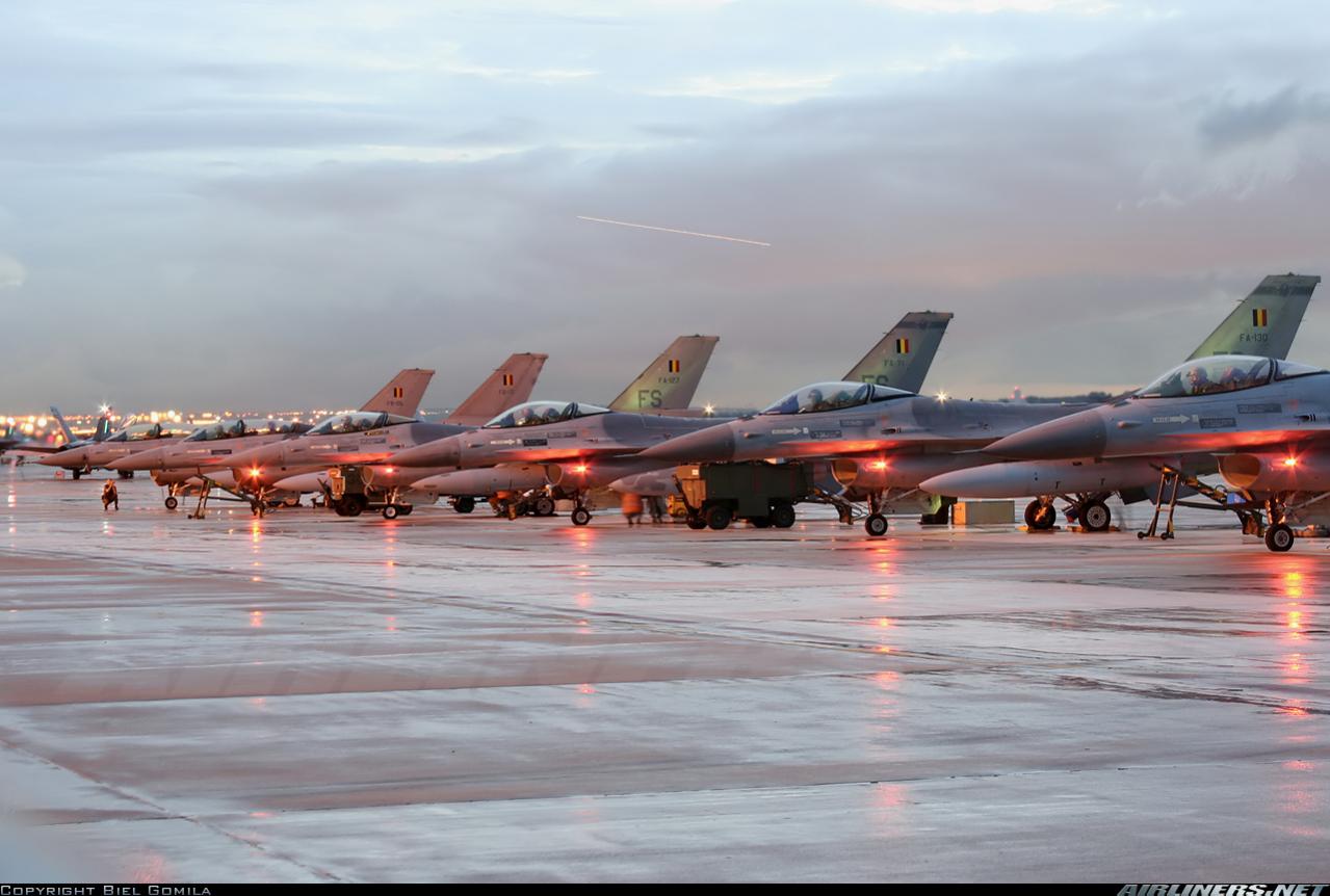
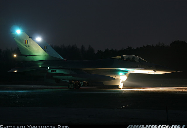
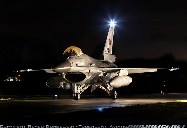
I continue my research on F-16 lighting system by observing the real F-16 pictures....
|
| |
| a p l a c e RC&E HOBBYISTS m e e t | |

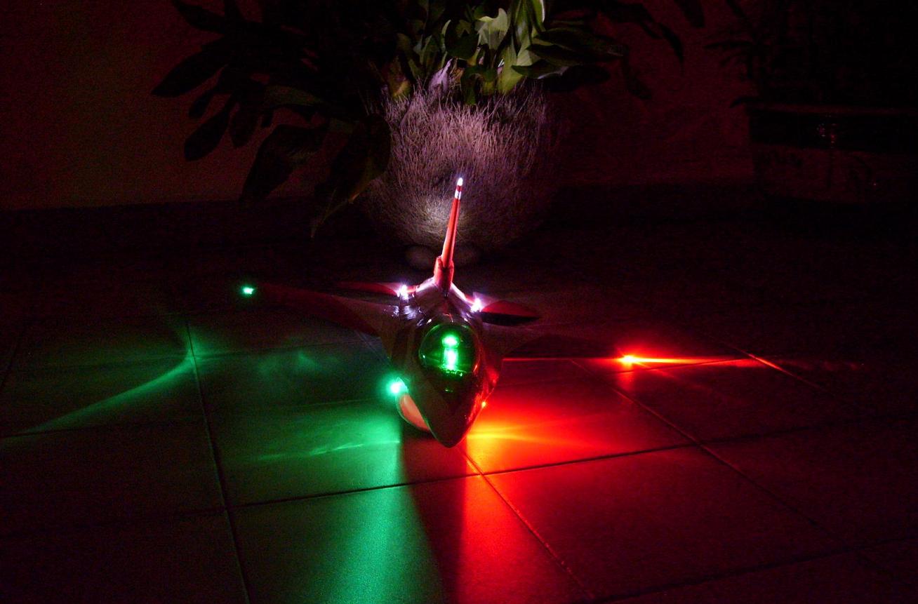
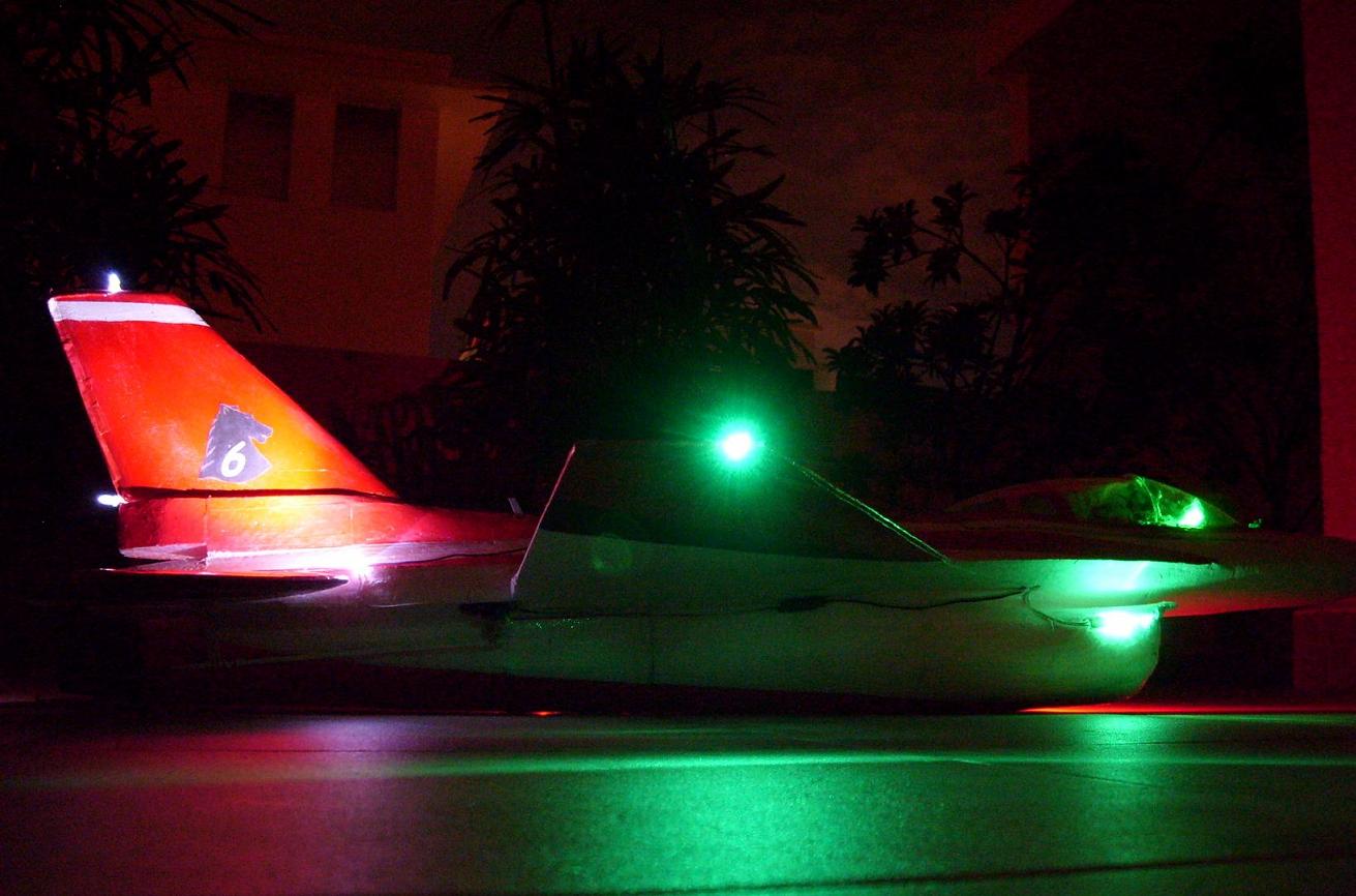 . Just simple aim the LED at the F-16 vertical stab like how you aim a laser pointer at someone

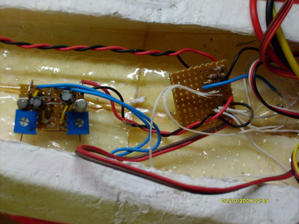
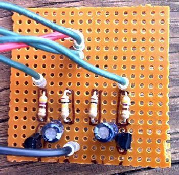
 ,On the other hand, 0.5 - 1 watt LED came in prices like 80cents a piece. RED leds are cheaper while the blues are more expensive,probably because blue LED came into production in the early 1990s. Err..ok i'll stop here before i get carried away talking about LEDS . Just imagine everything inside the plane is one circuit and performs one job...thats is to make the F-16 fly with lights on I use to have plenty of em. accidentally blow them by pumping in 12volts directly accidentally.
 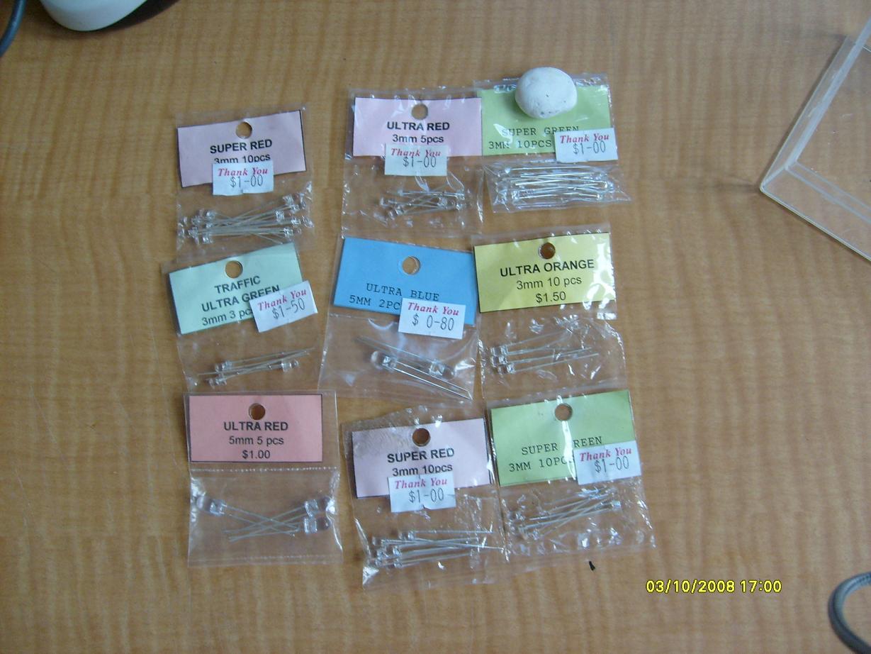 .
.
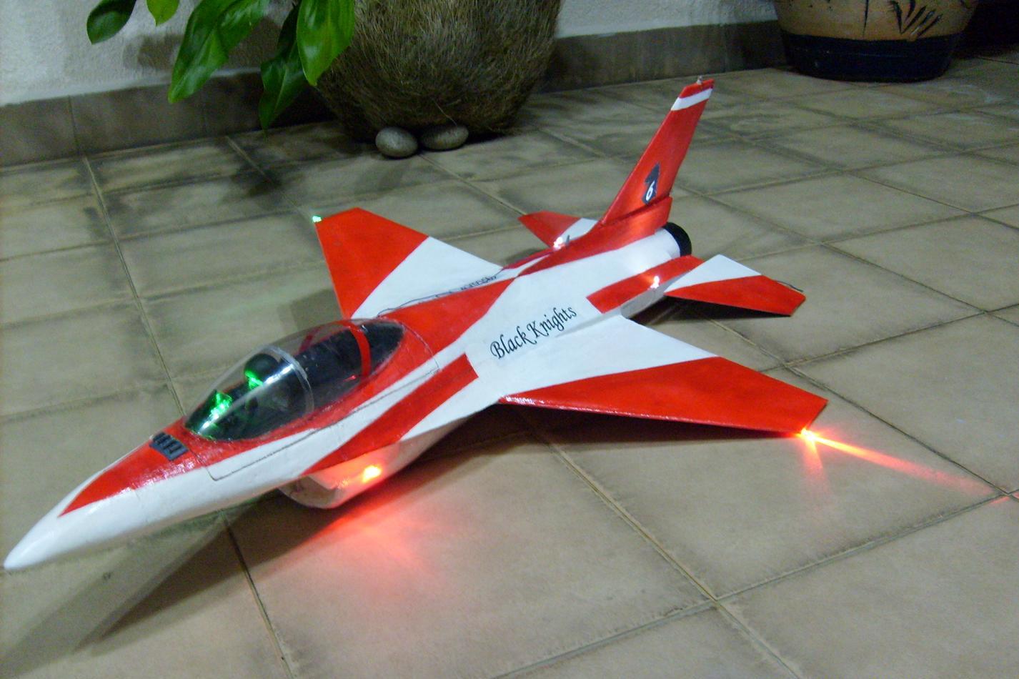
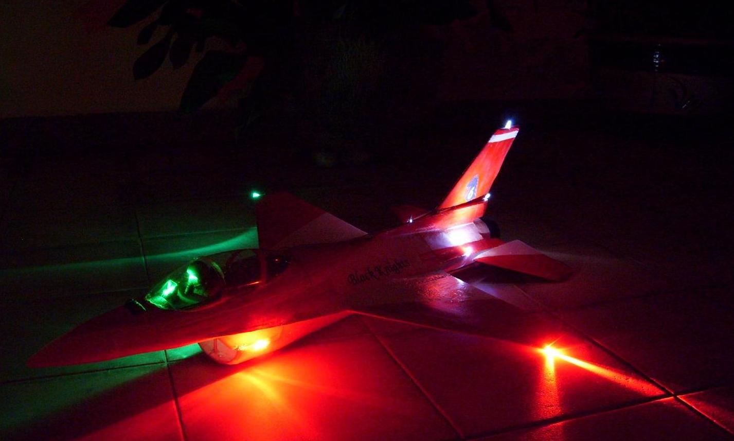
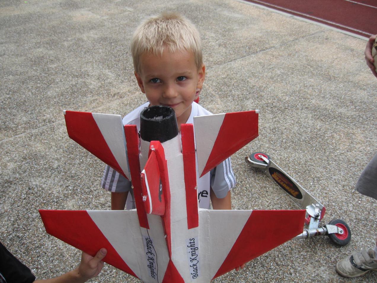
 so kawaii!!!
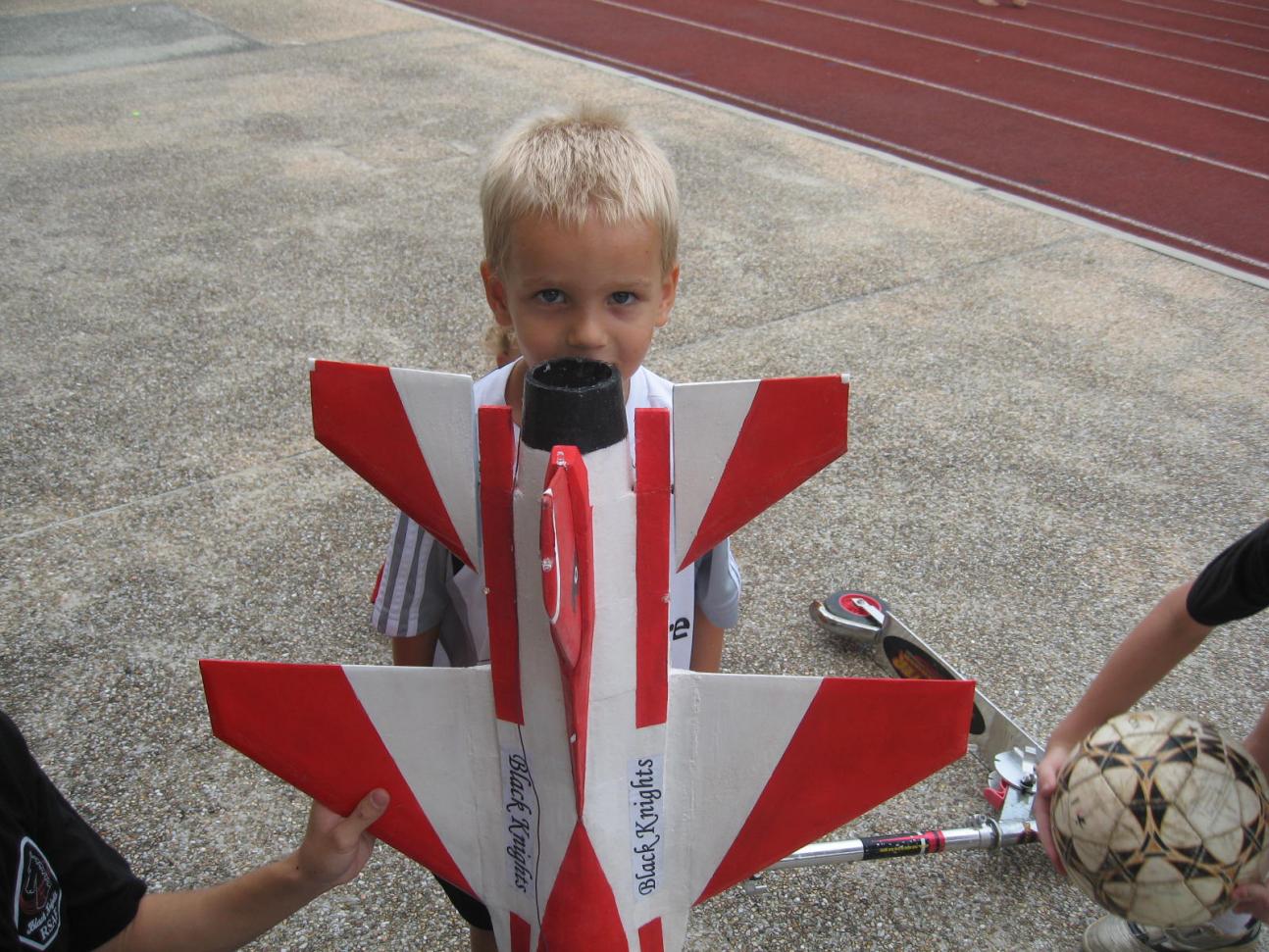
Comment