Hi Folks,
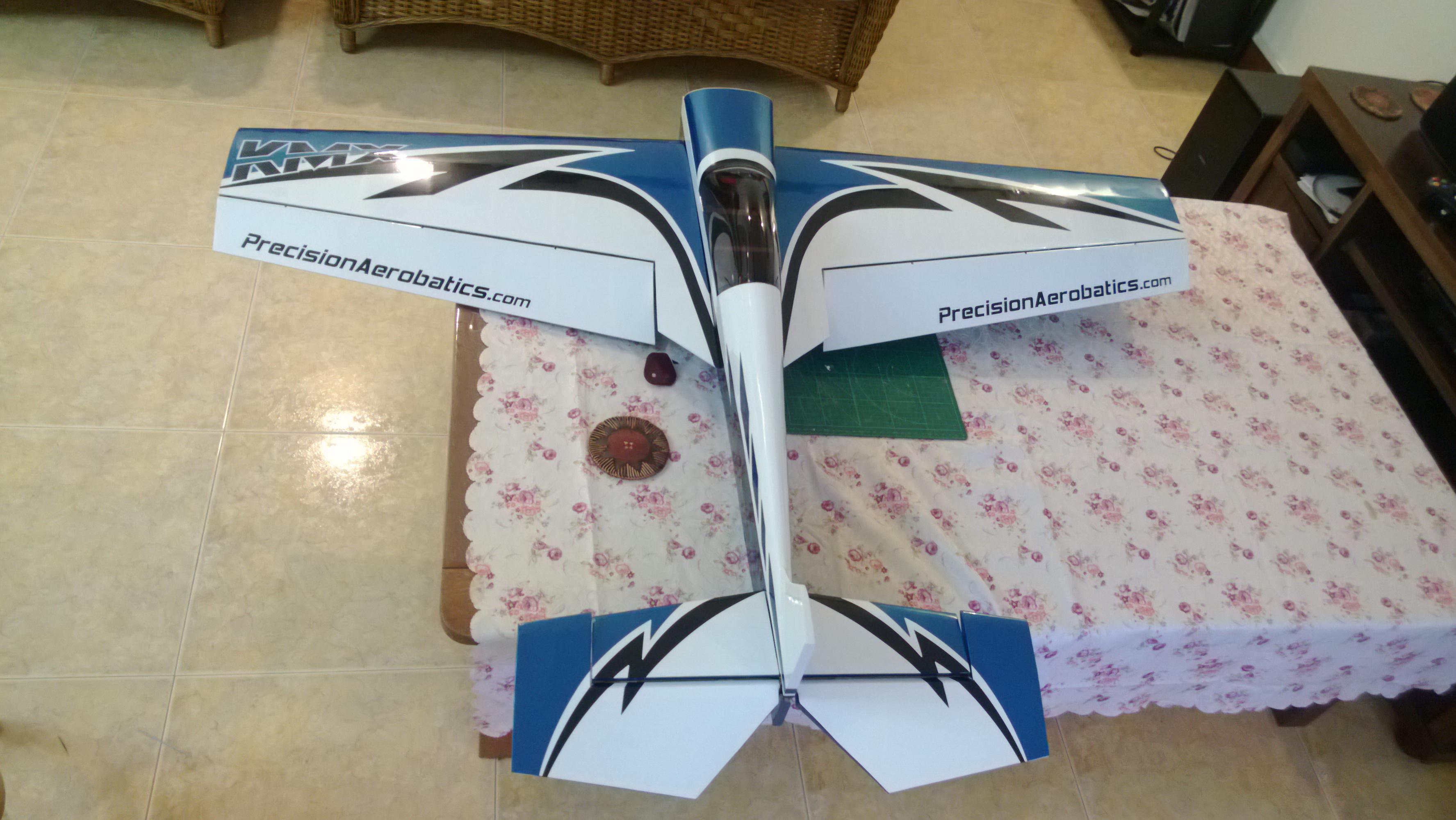
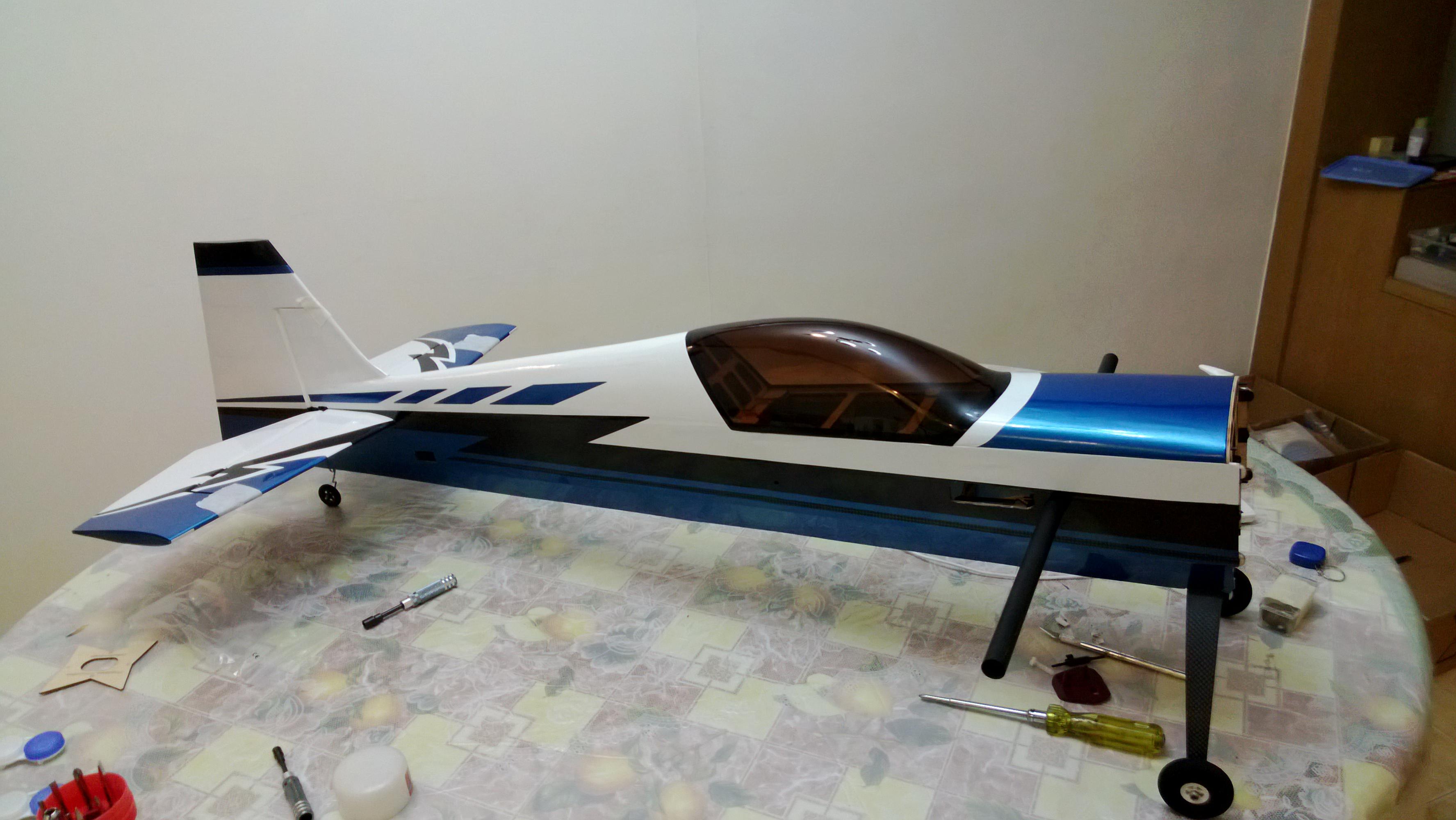
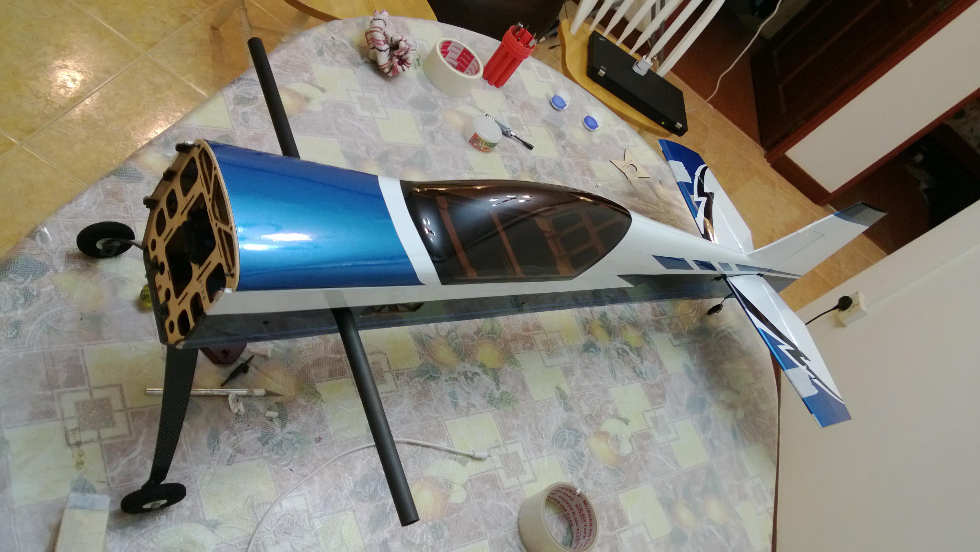
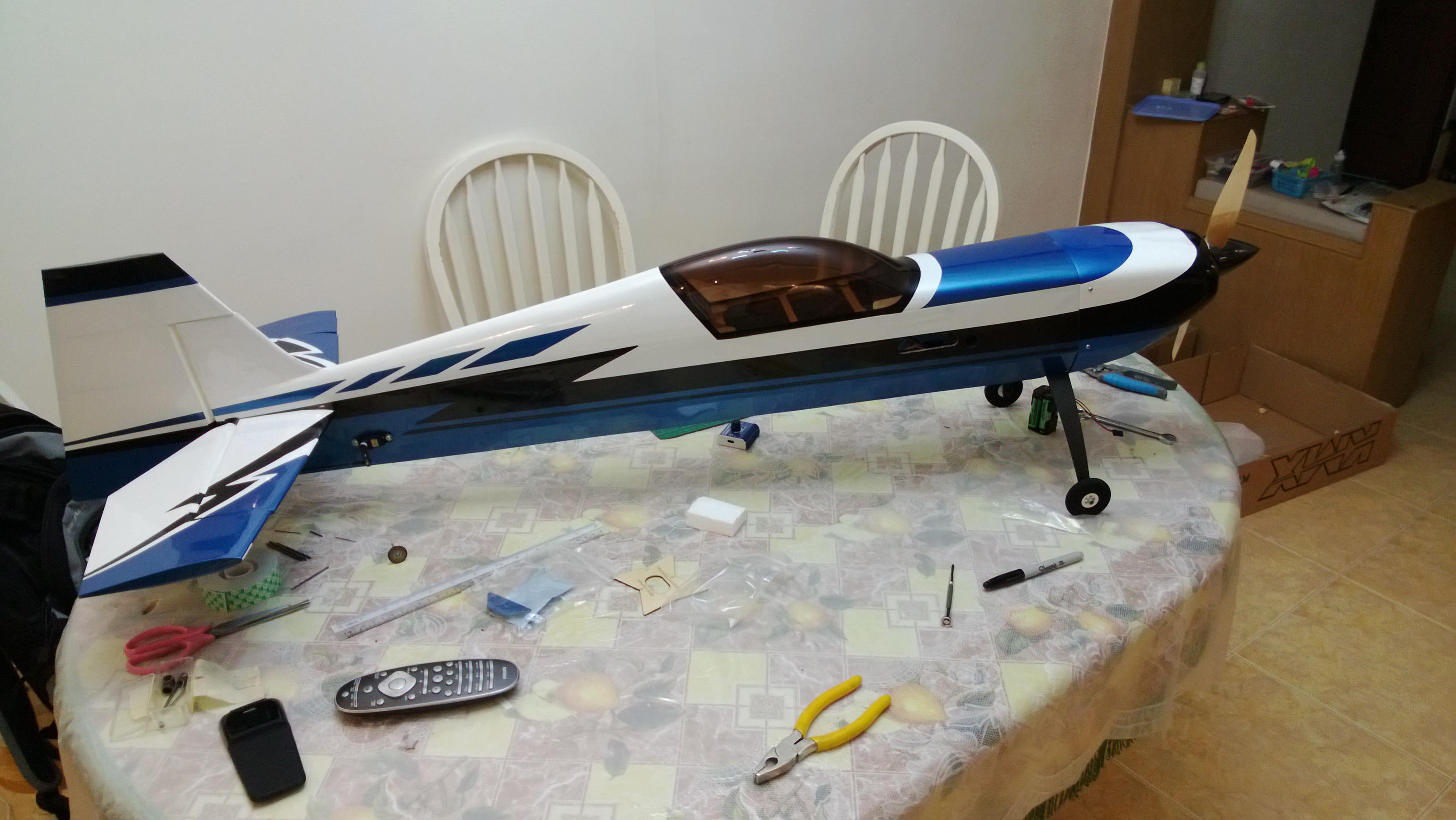
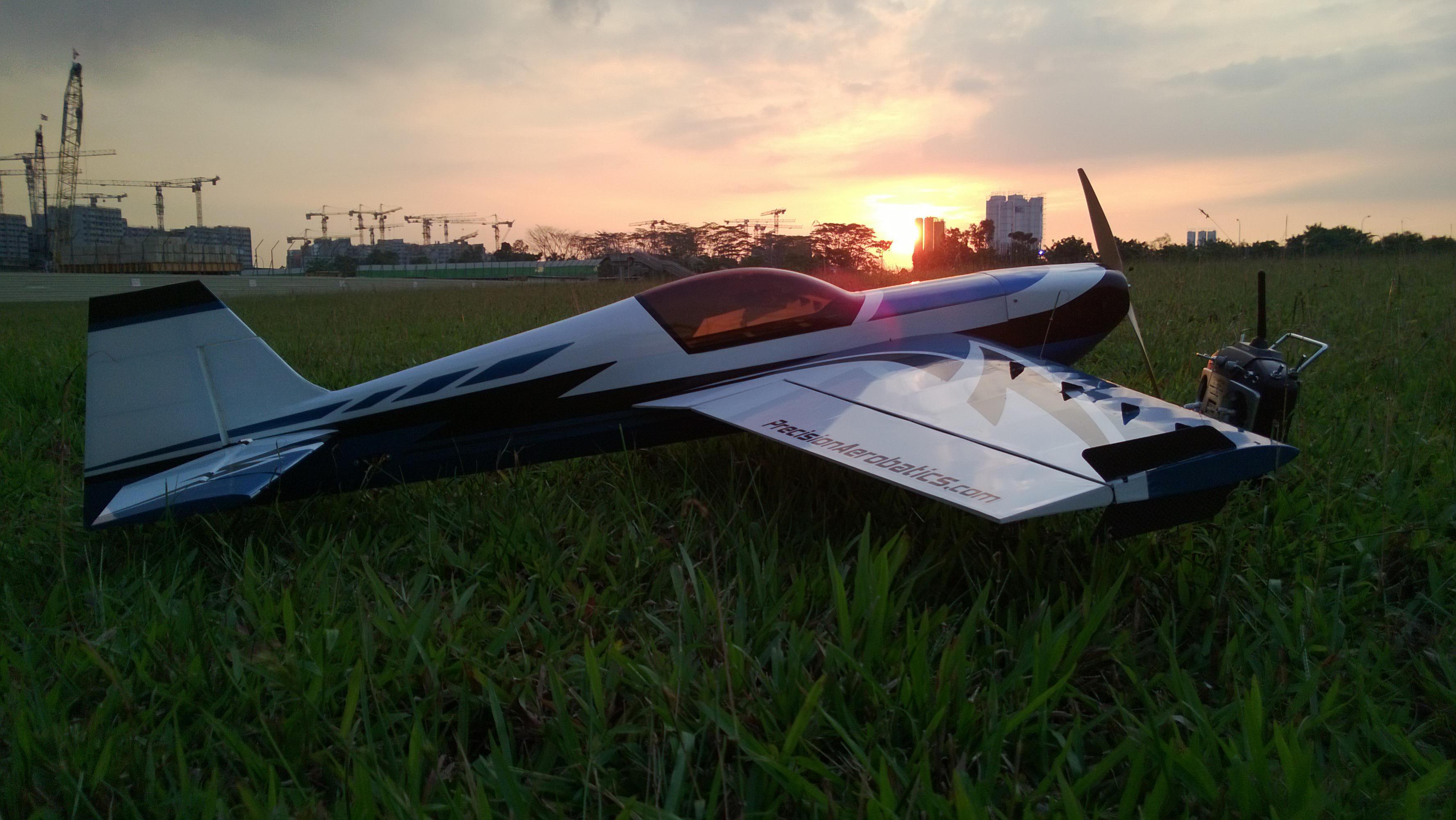
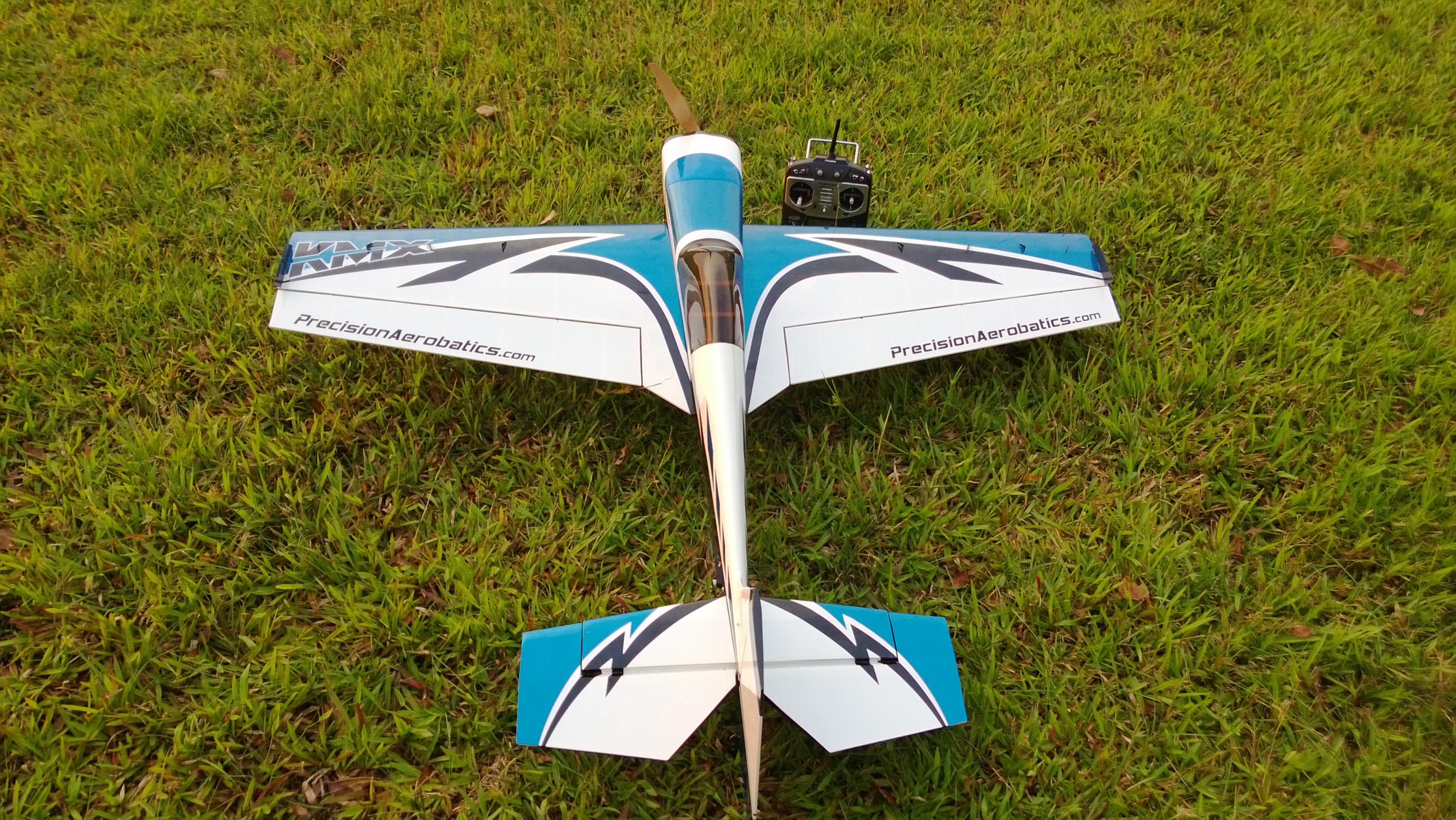
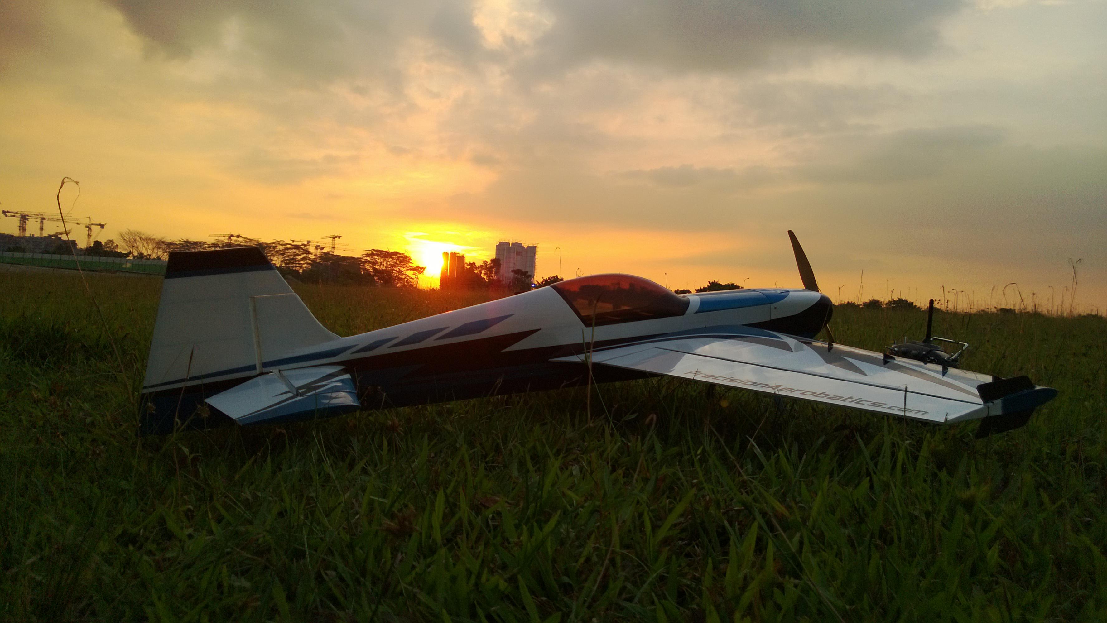
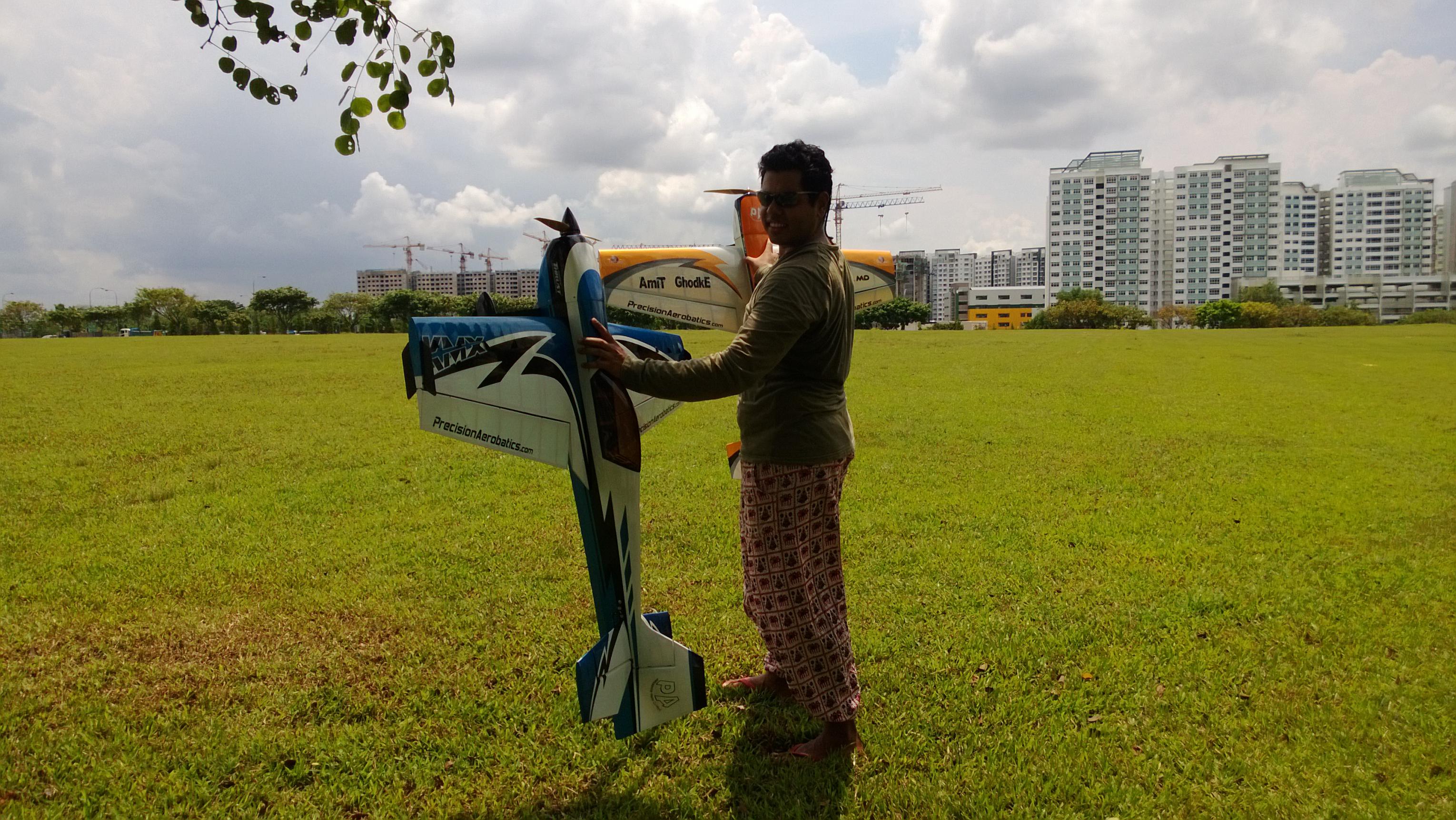
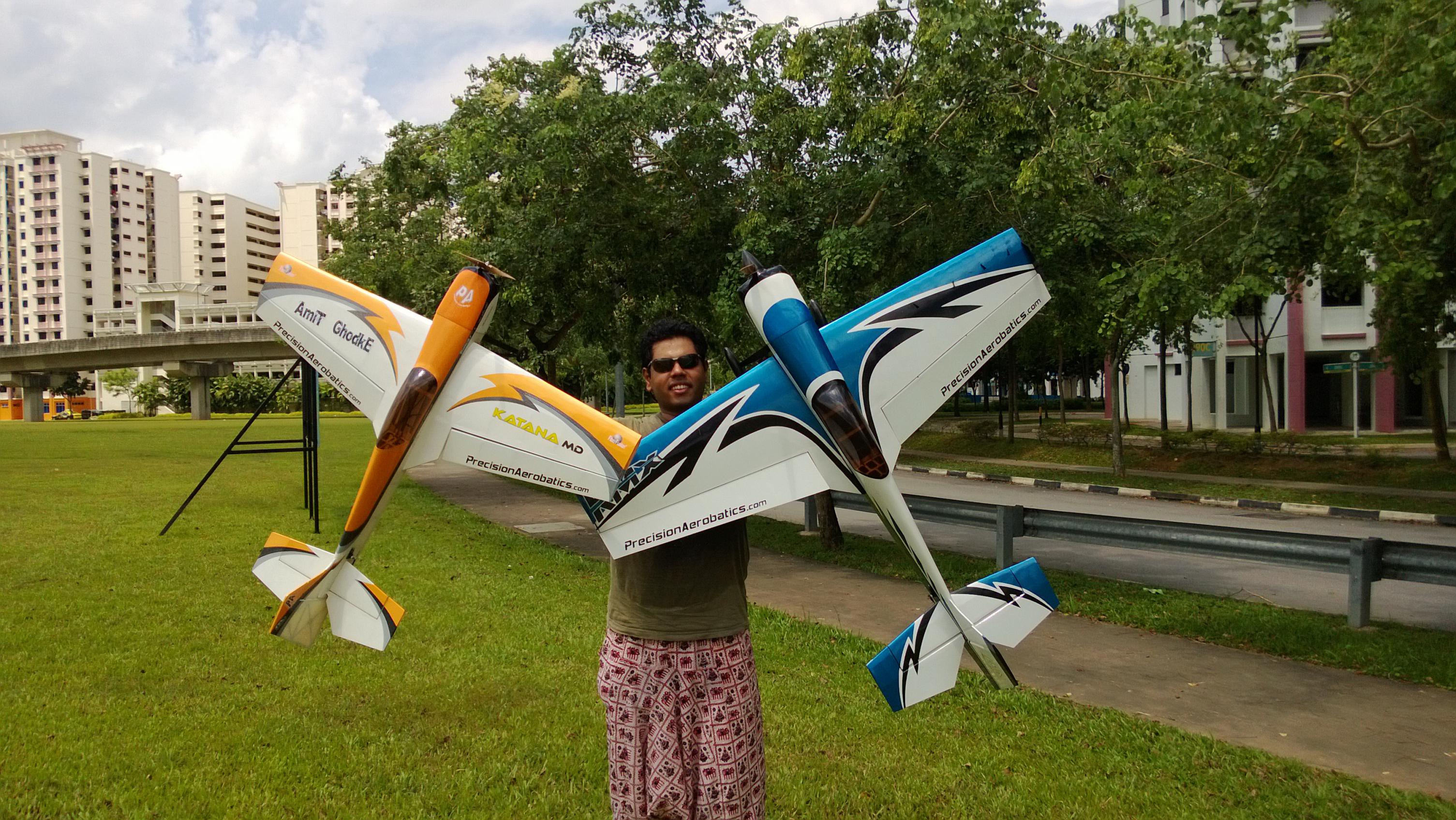
I have received my katana MX From Precision Aerobatics in short known As KMX and what a wonderful plane this is, just a treat to fly. Feels like a Giant Scale model.

The Discussion thread on RCGroups is here,

But i did not find a Build thread anywhere. Although very simple and straight to build like other PA models, i thought it would be worth sharing some info for anyone who is getting this for the first time.
Please feel free to chime in with your suggestions and Build details.
I am using complete IPAS setup as recommended by PA for this plane, Details can be found on there website.
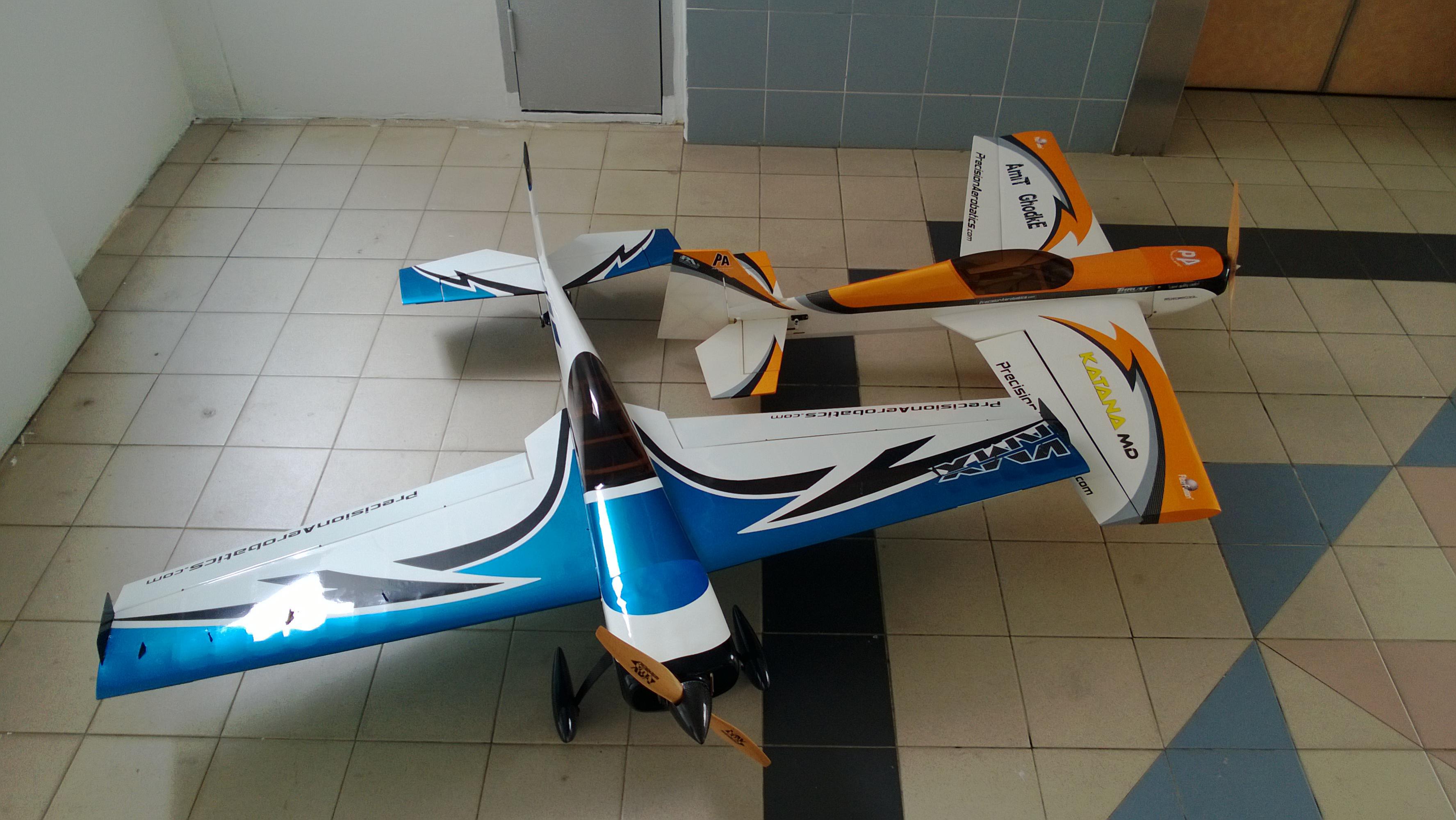
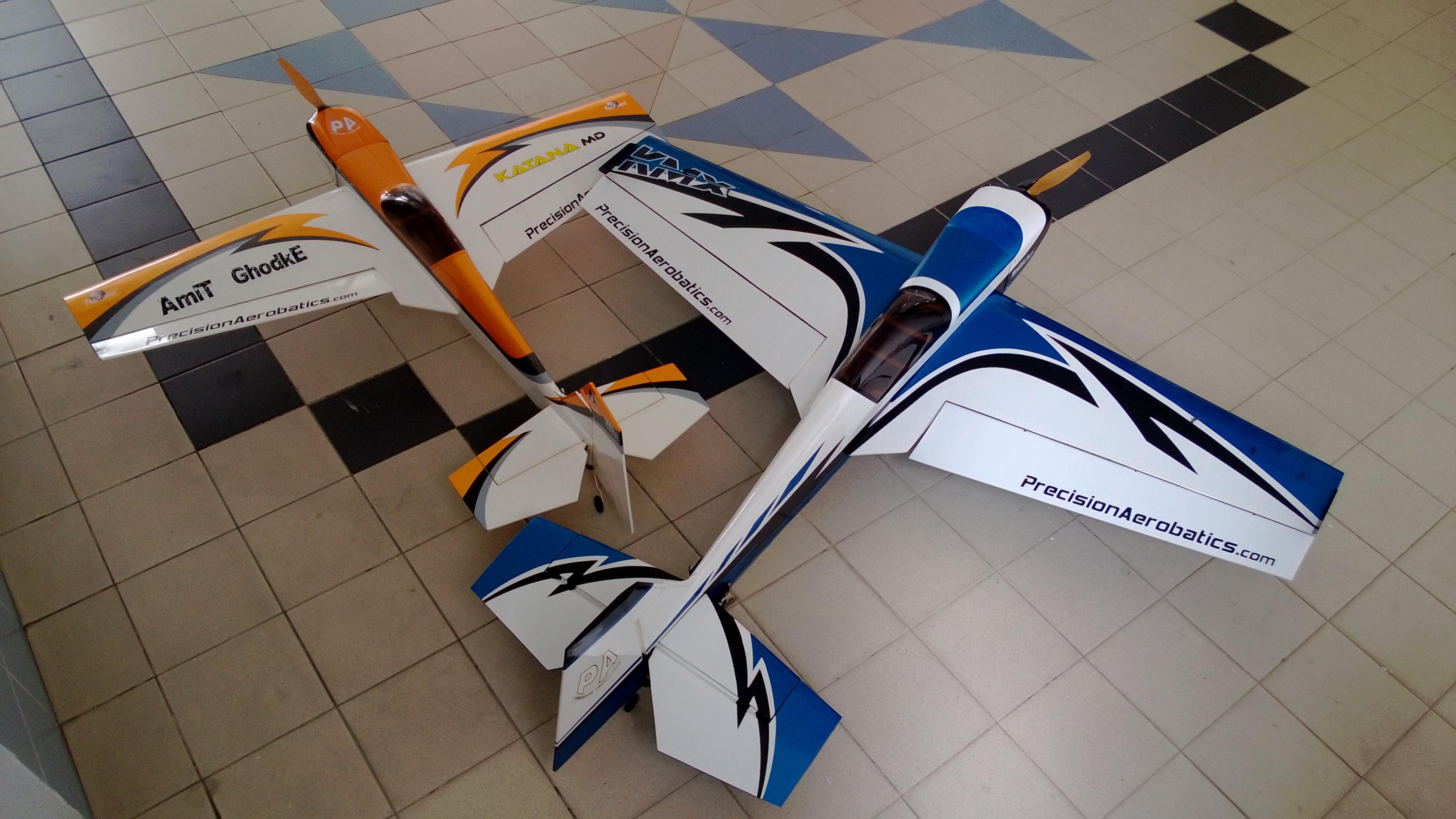
First Look at this plane and i can tell you i loved it. I own the PA ExtraMX, AddictionX, katana MD and Bandit (Still in box).
Seems like there is quite a bit of improvement from the ExtraMX construction :-
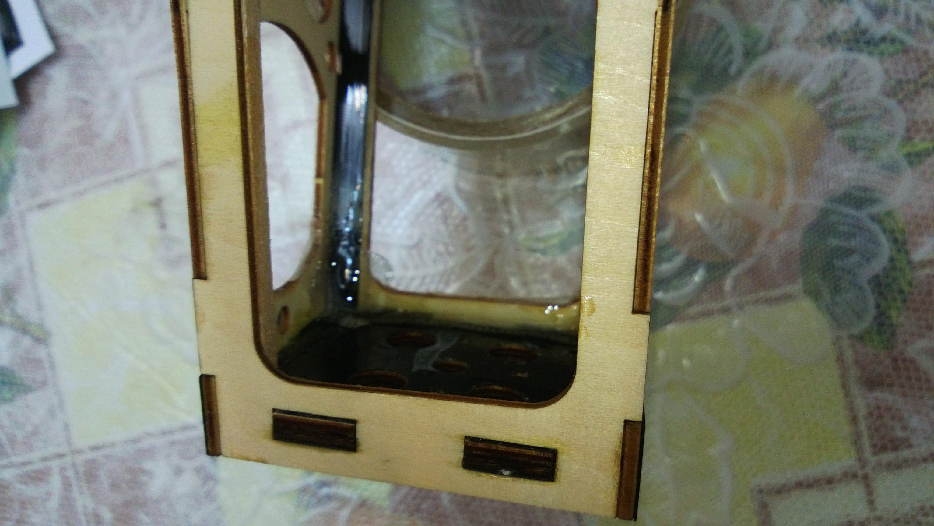
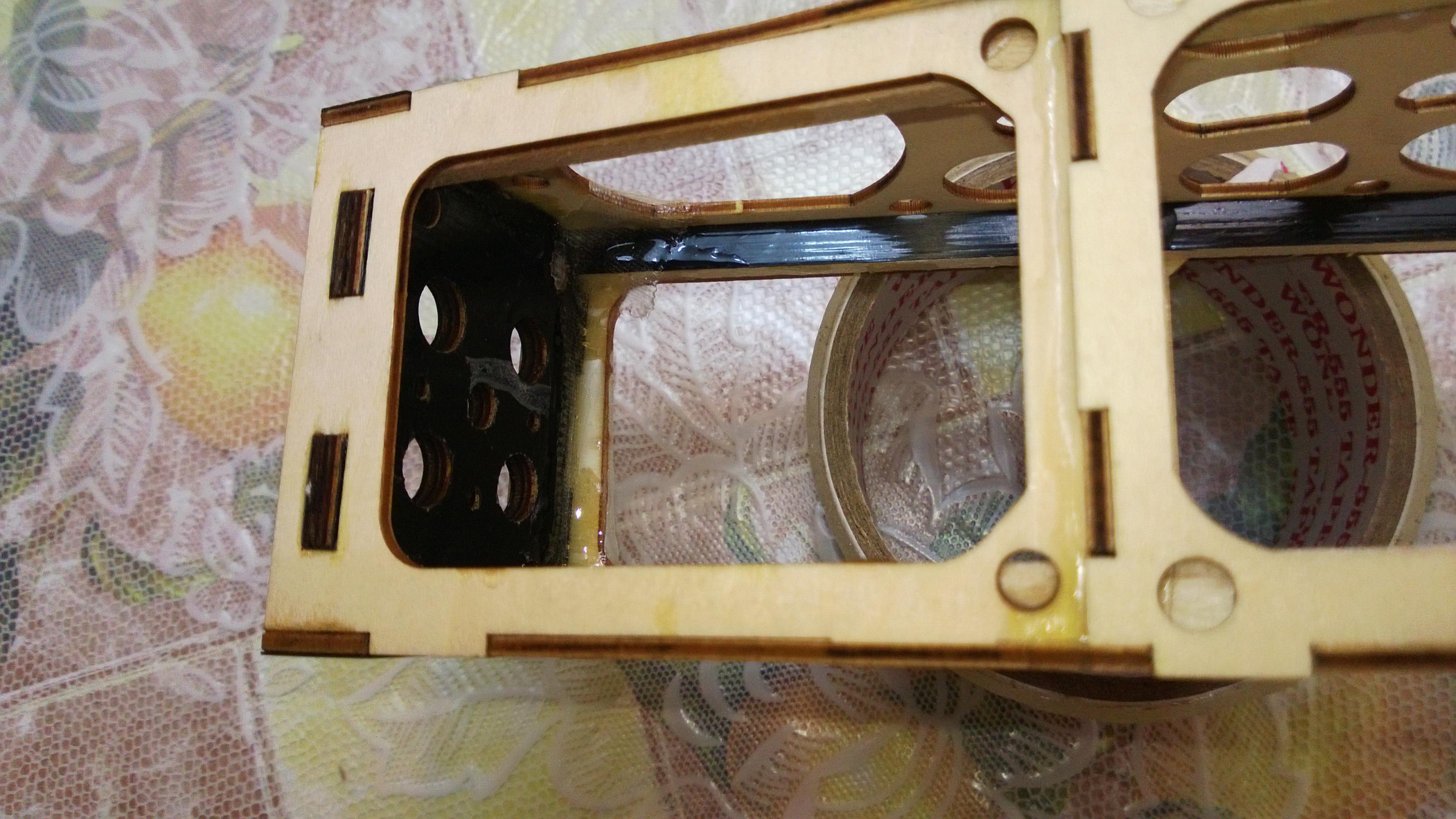
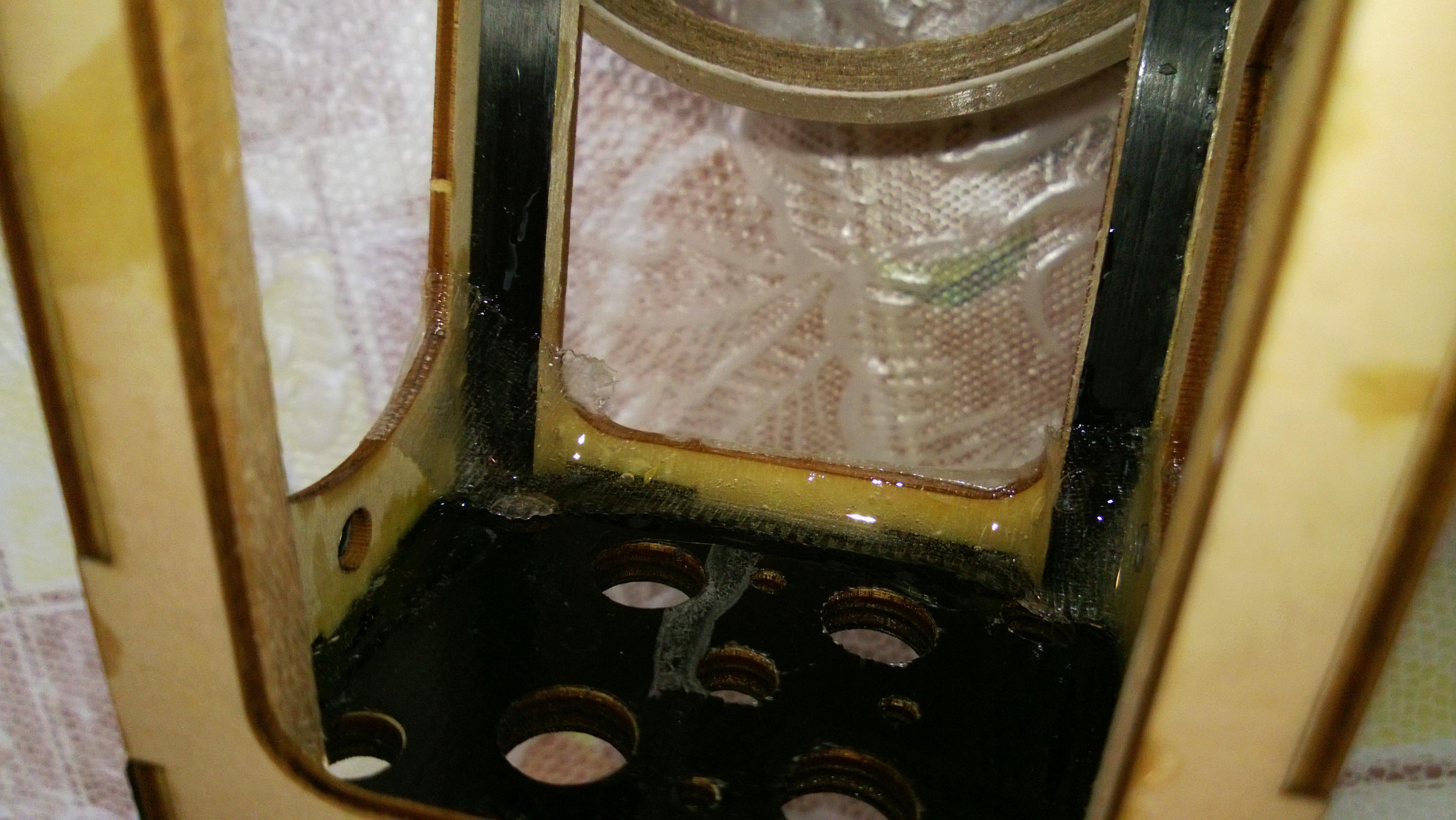
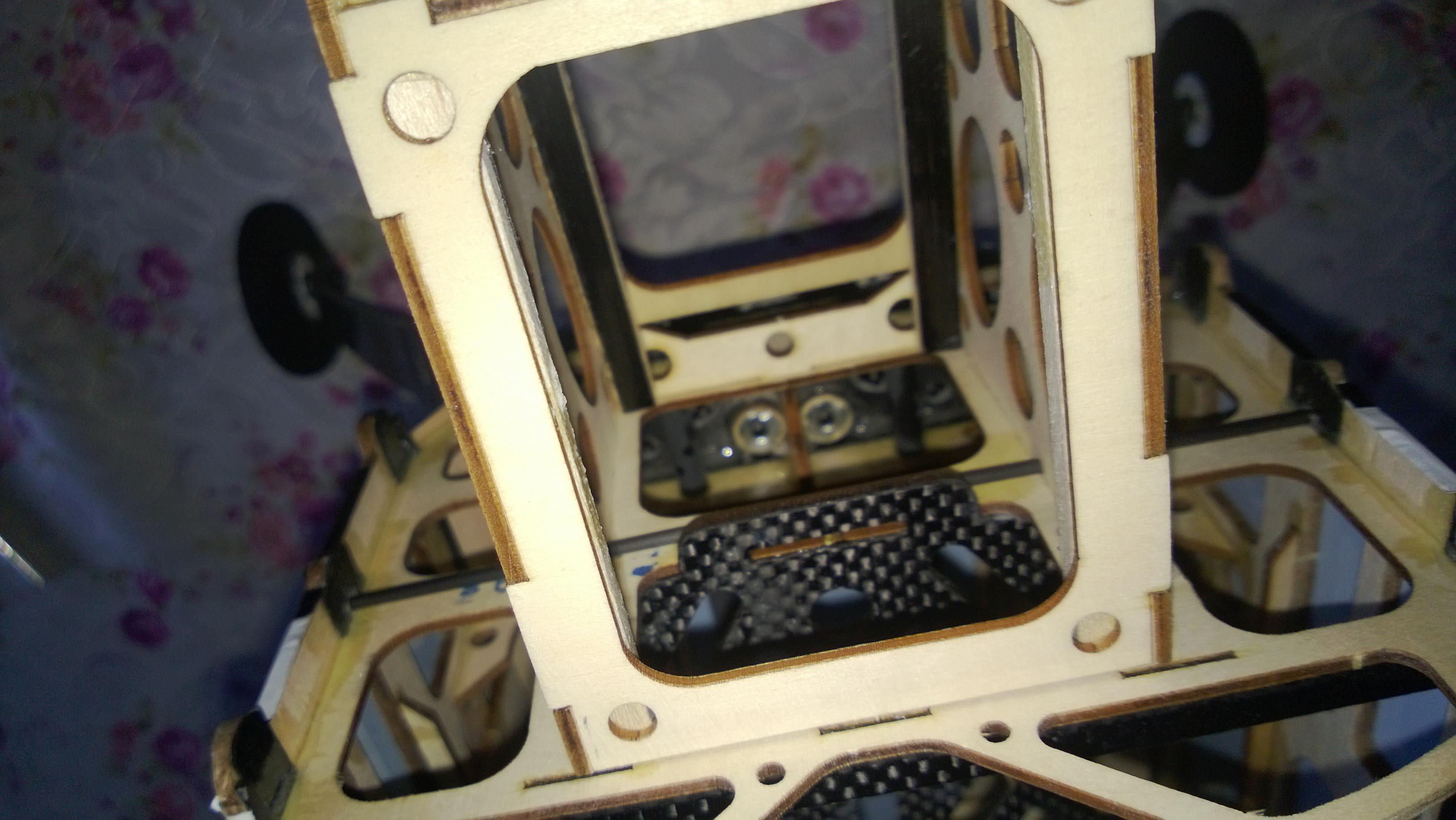
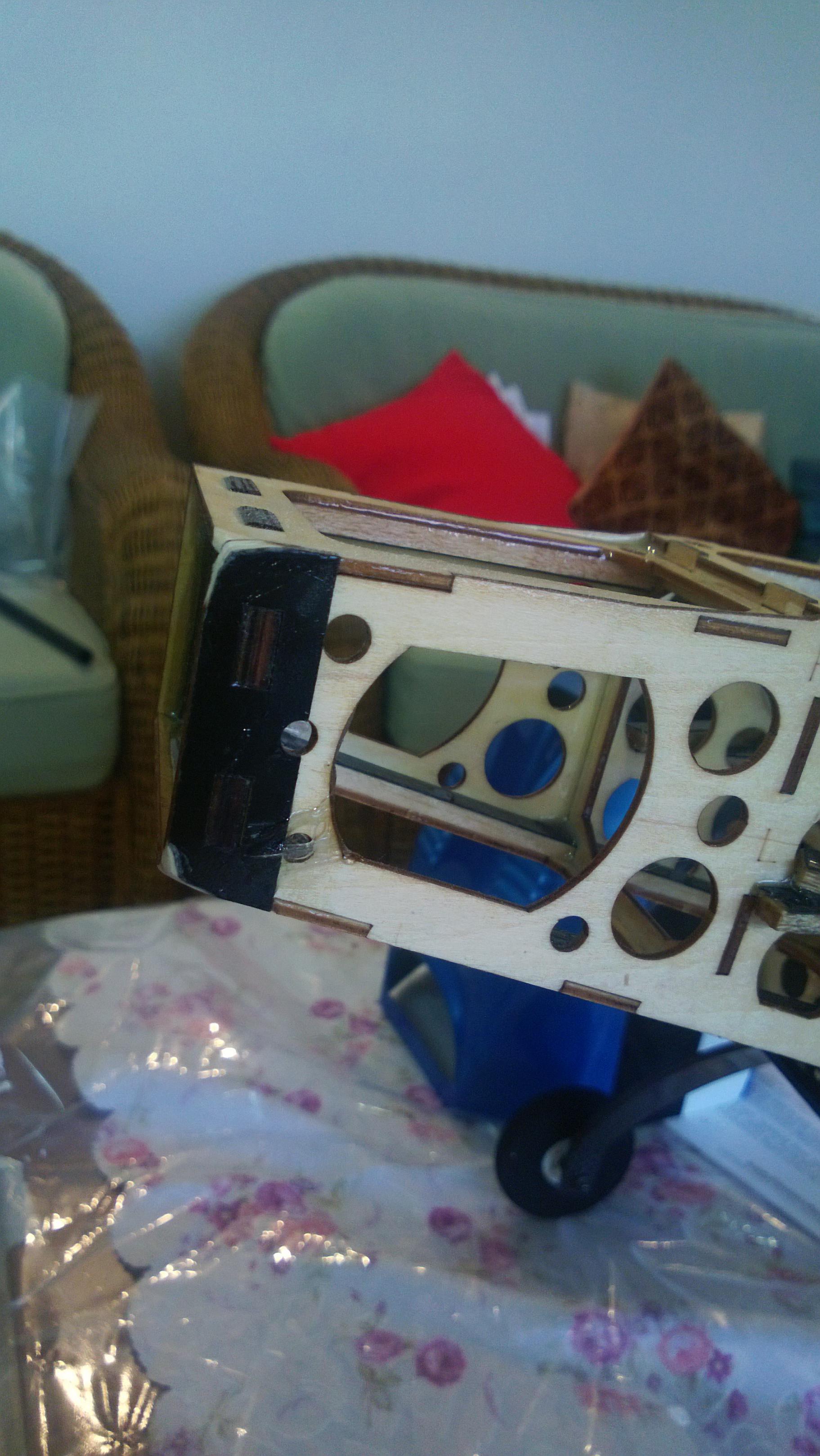
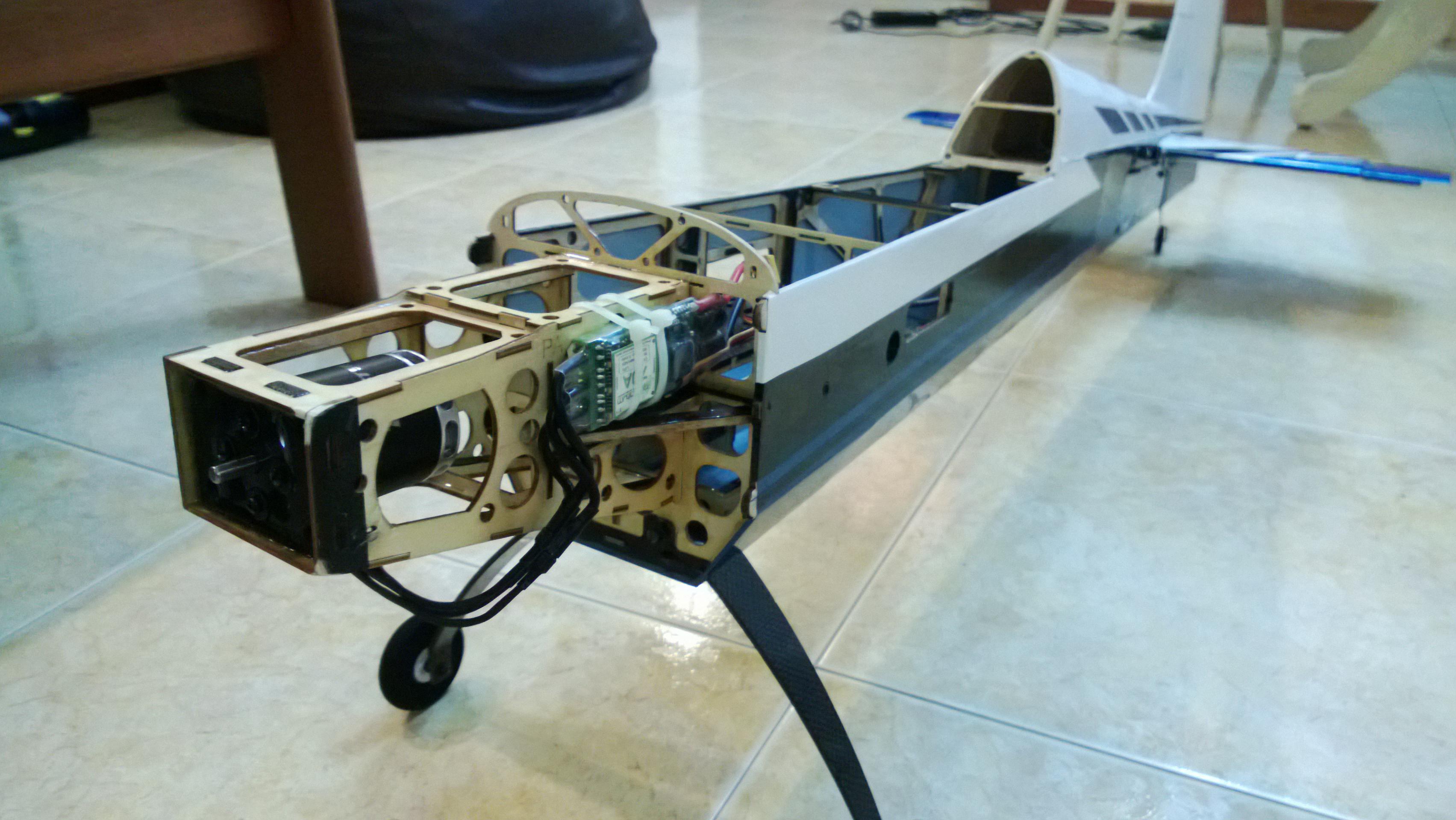
- The battery tray comes up unlike going down in my Extra MX this to me seems like is a big change to save the balsa near the LG area from shattering and breaking during those not so soft landings. ( The KMD has it this way). My Extra MX does have the cracks all around here over the period of time.
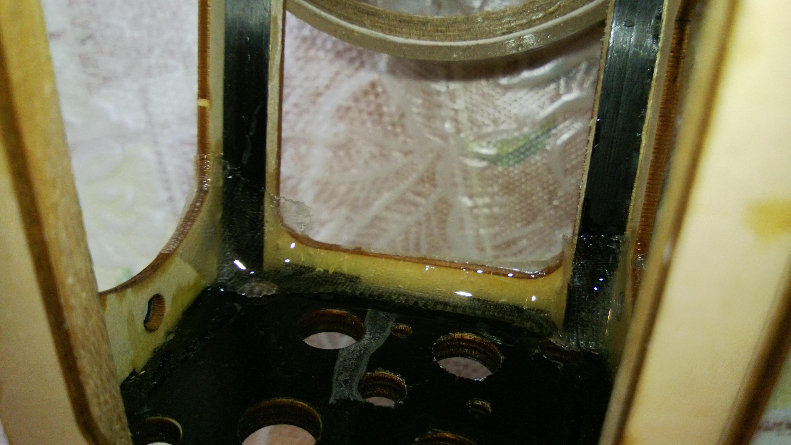
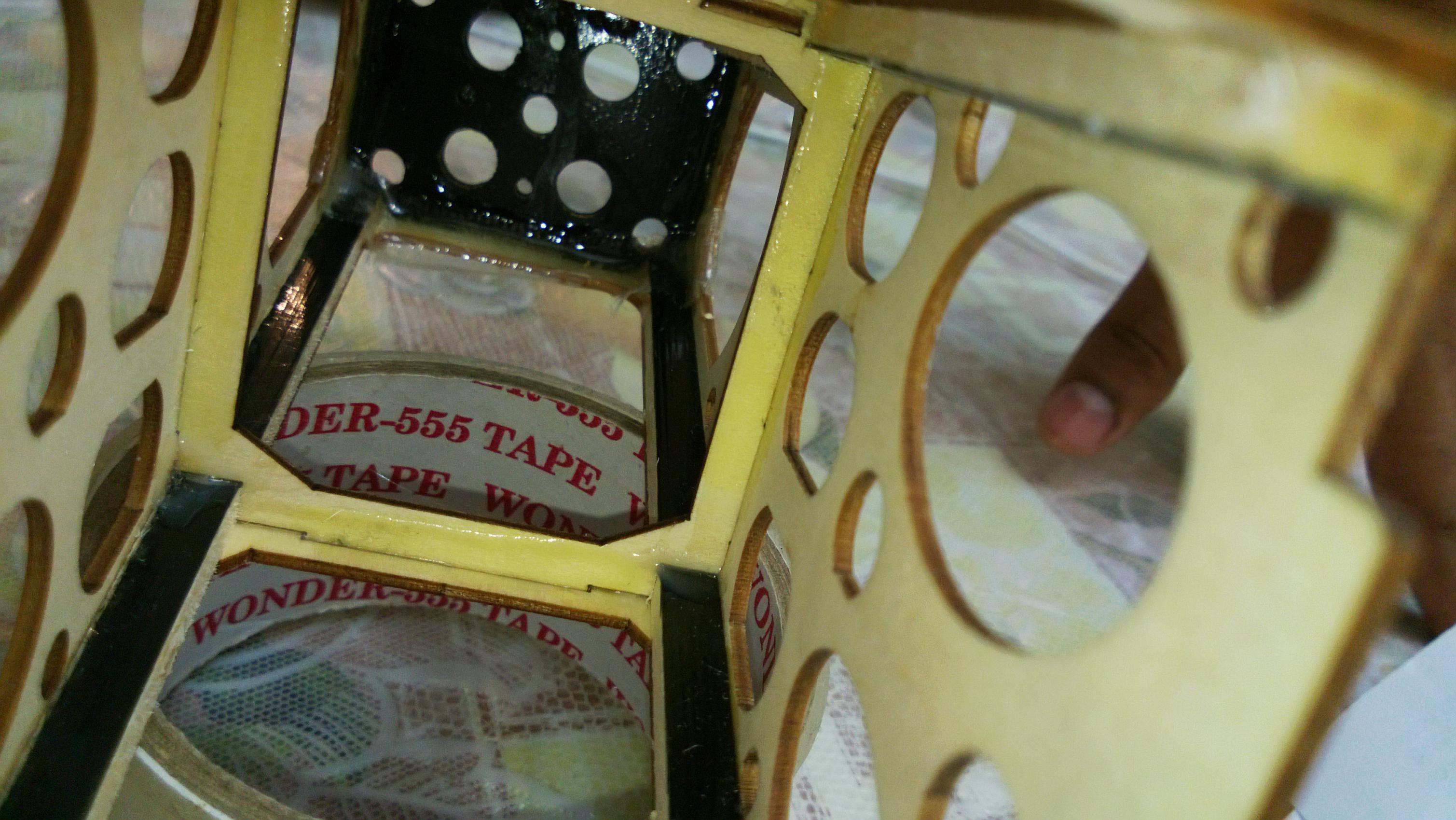
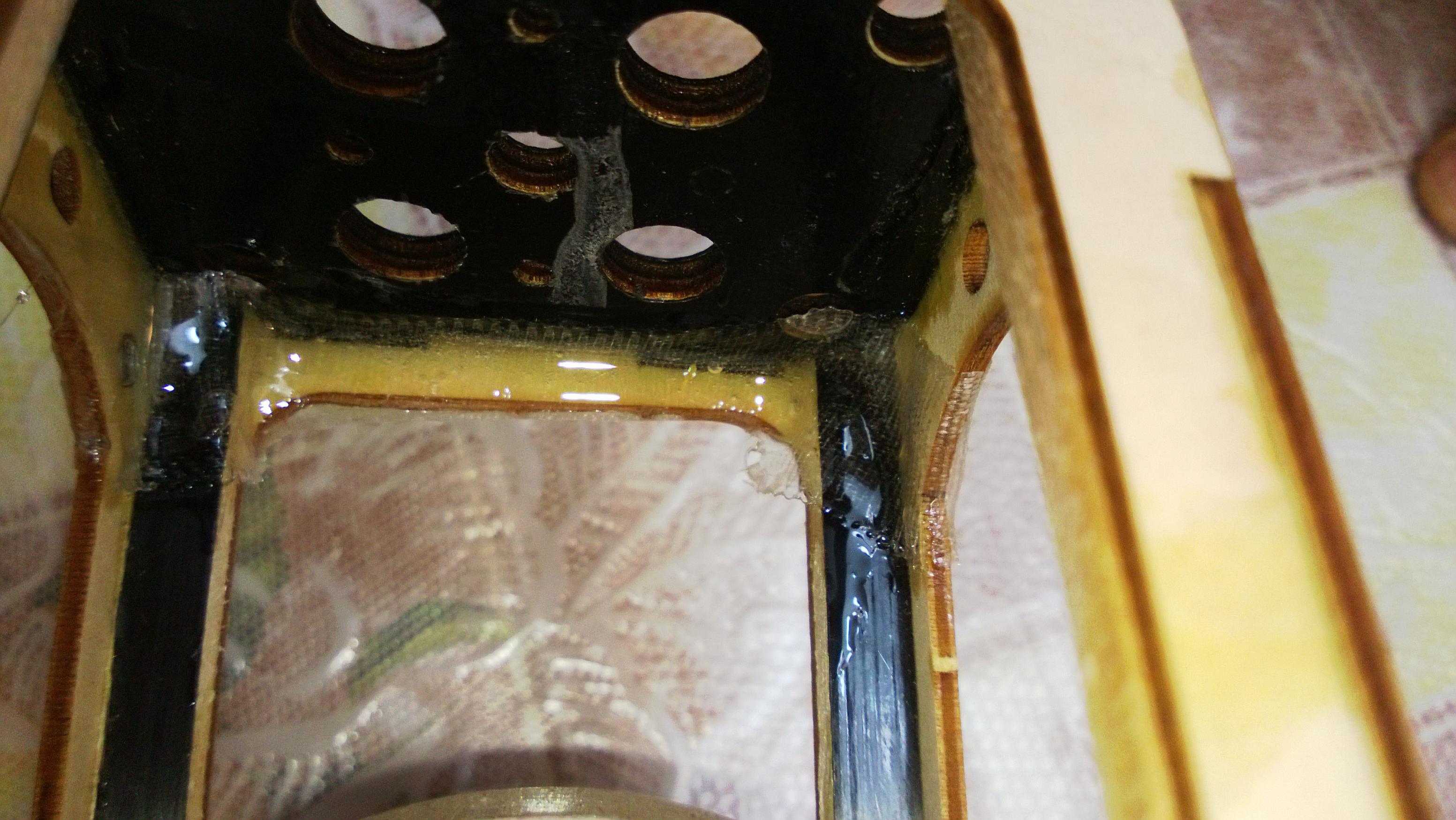
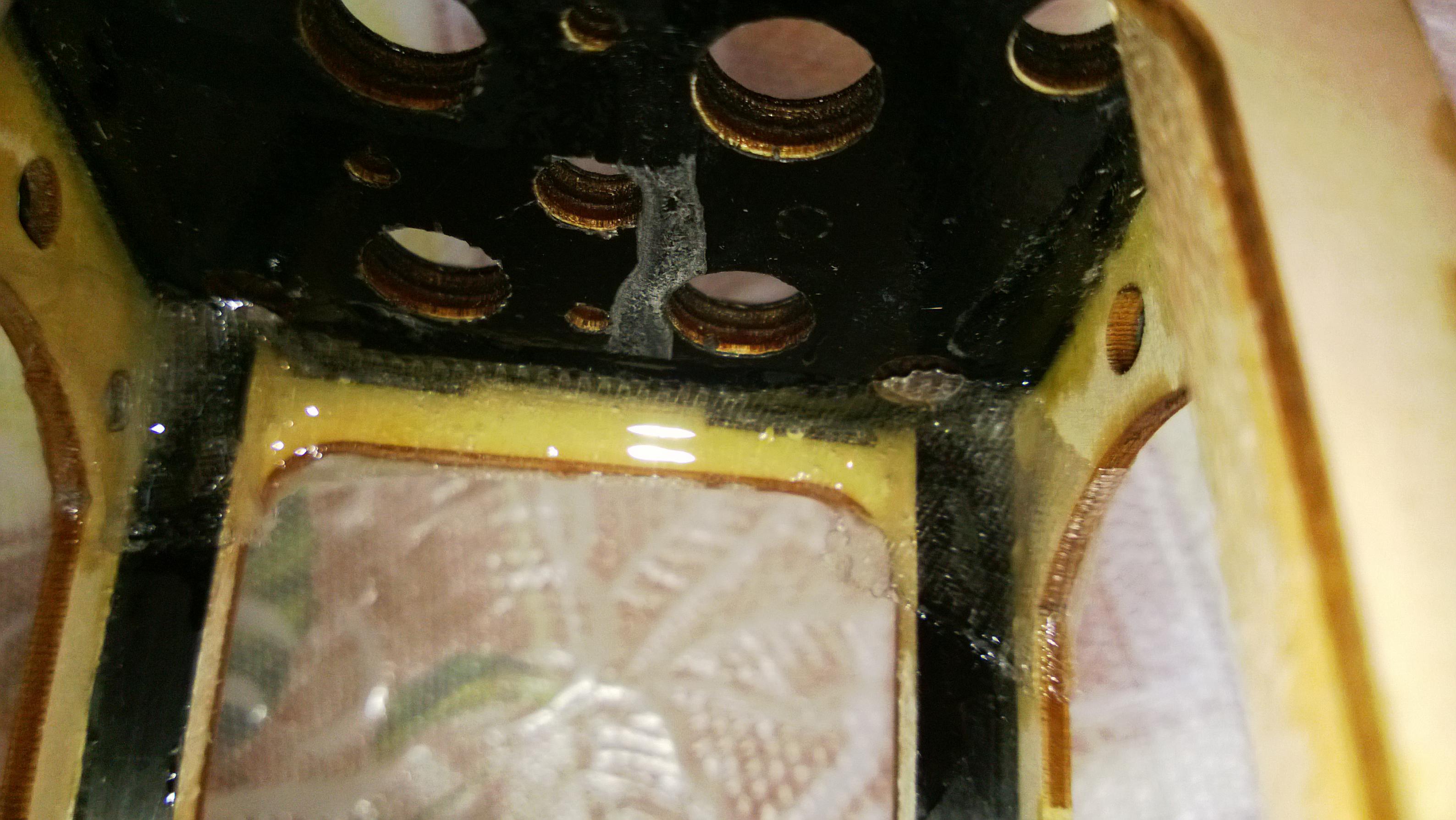
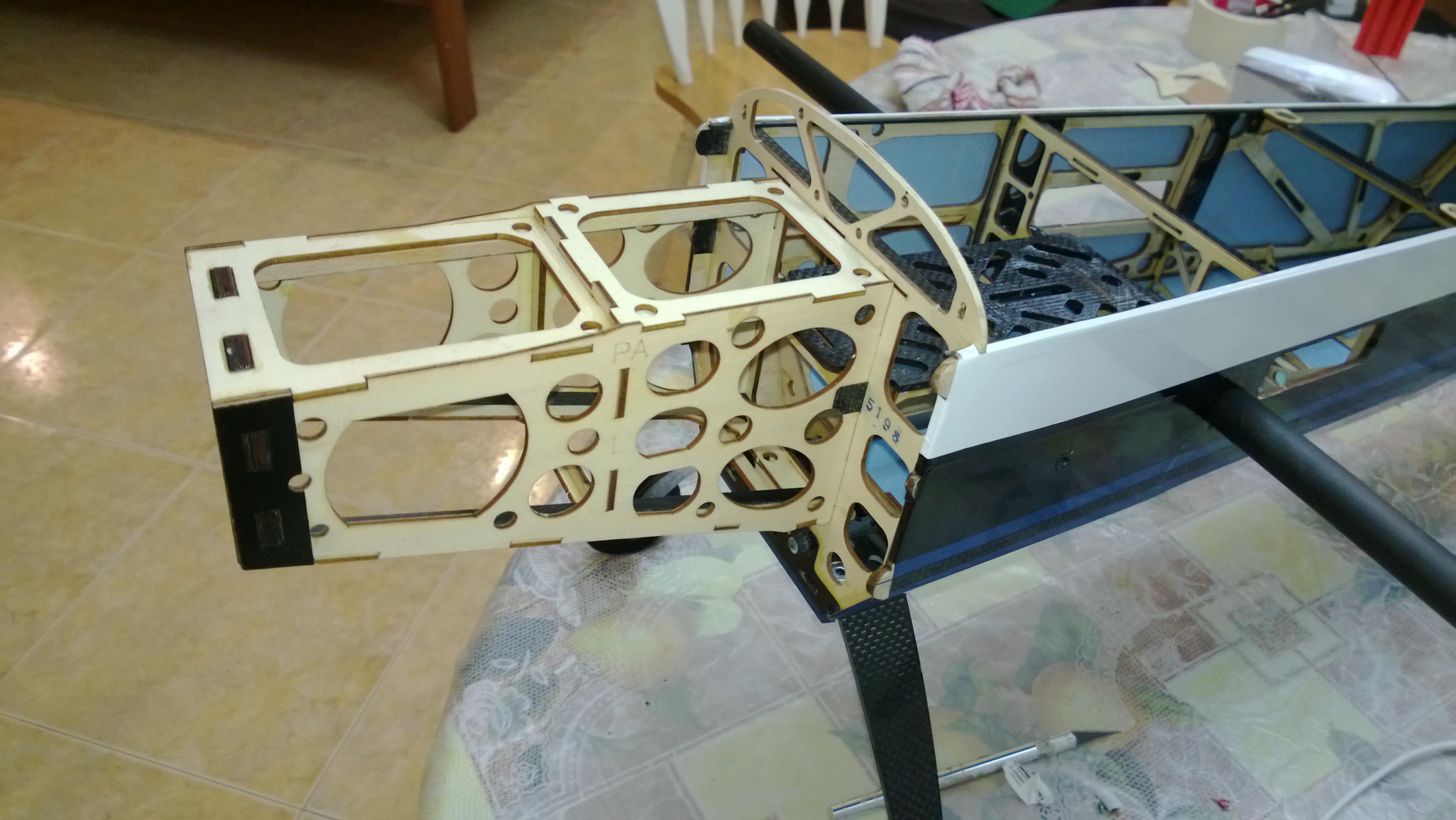
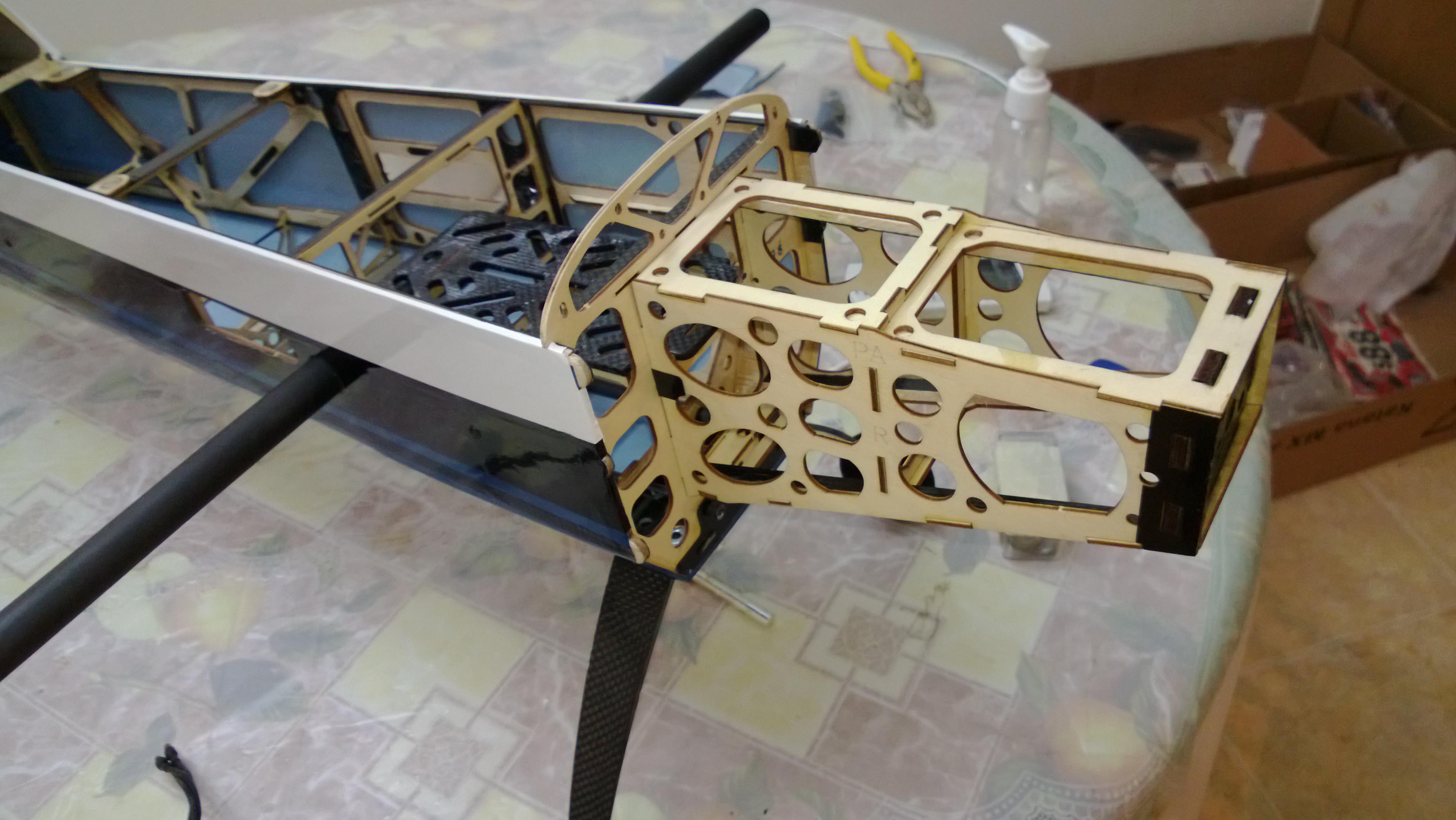
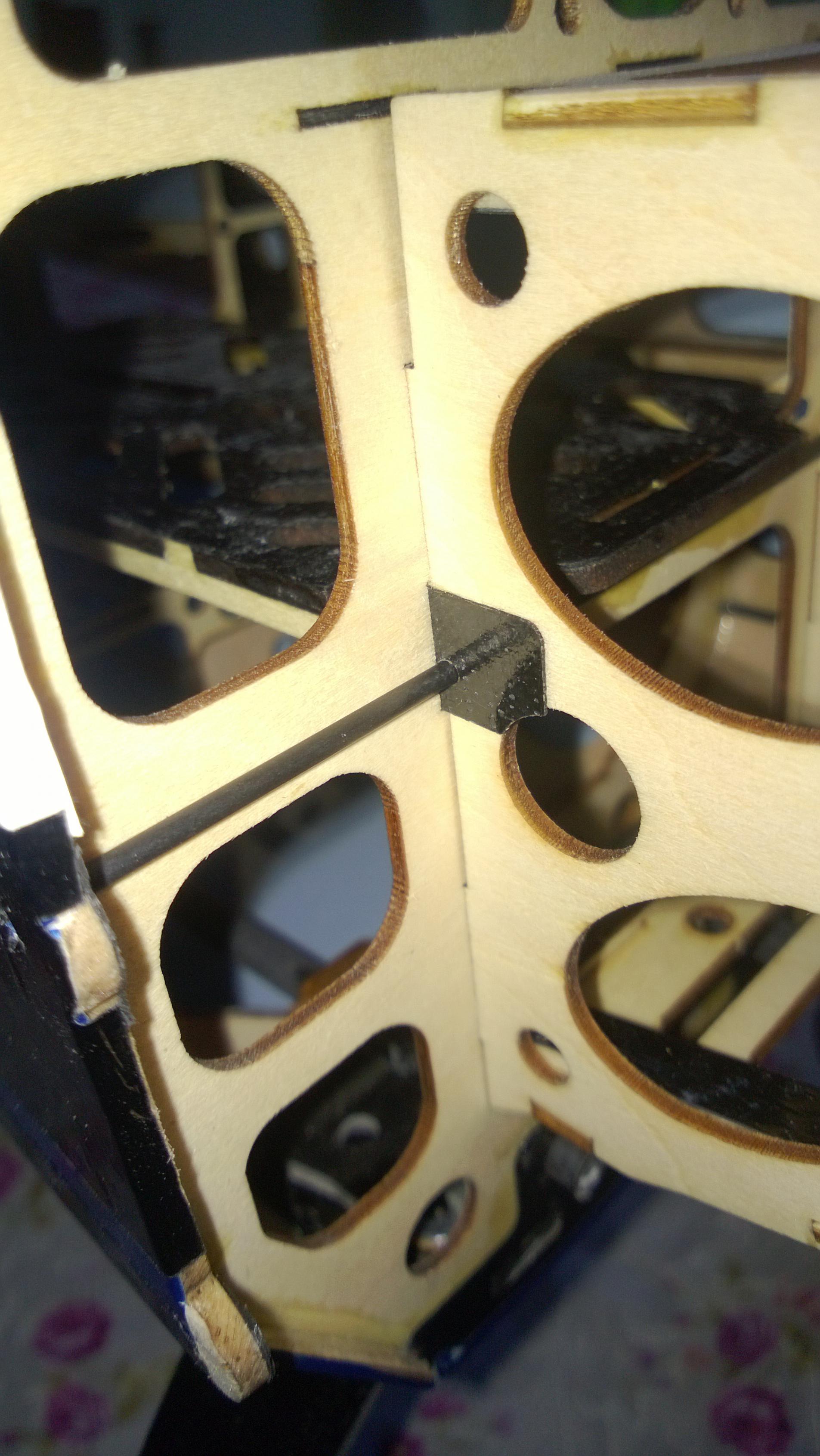
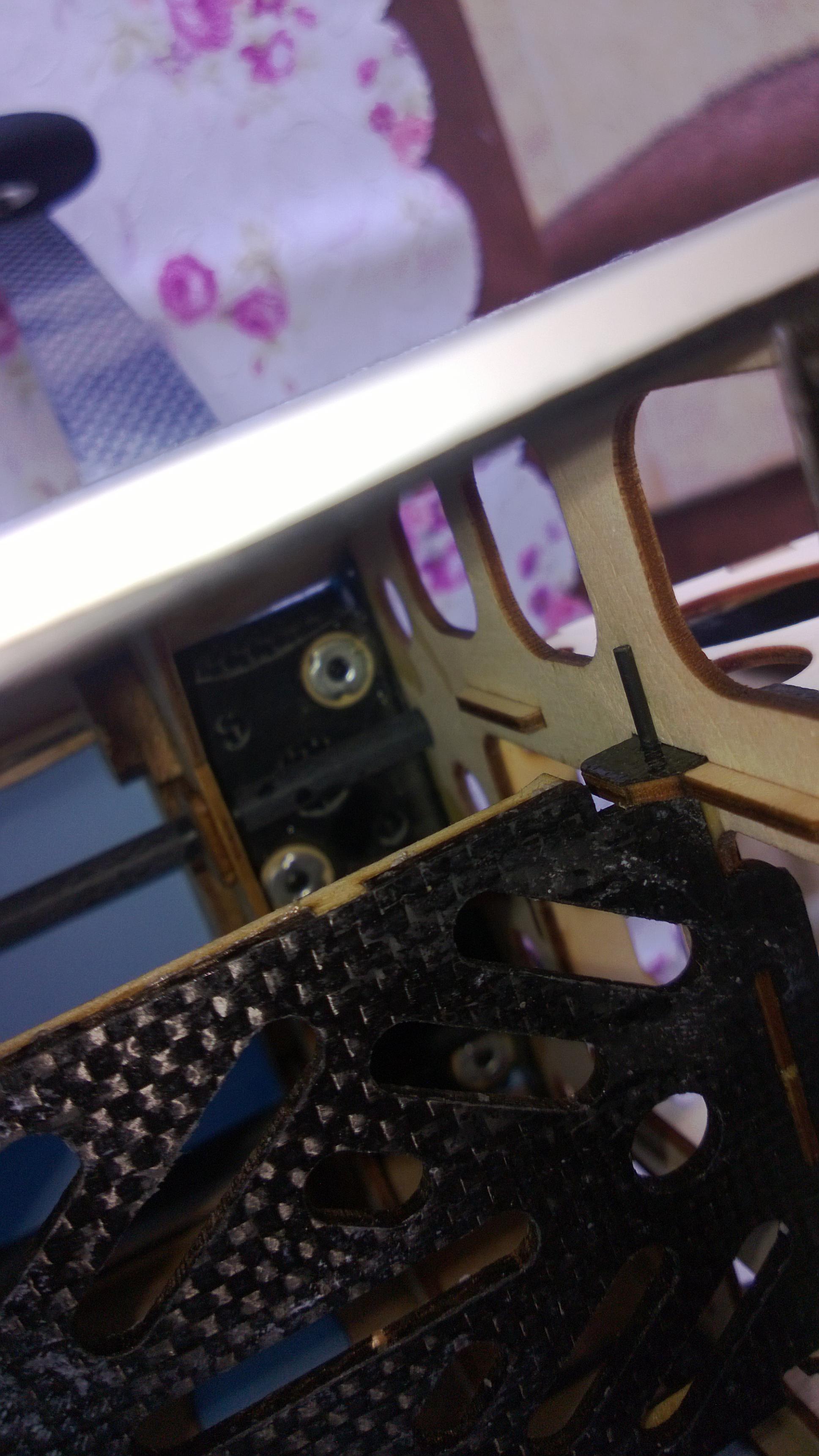
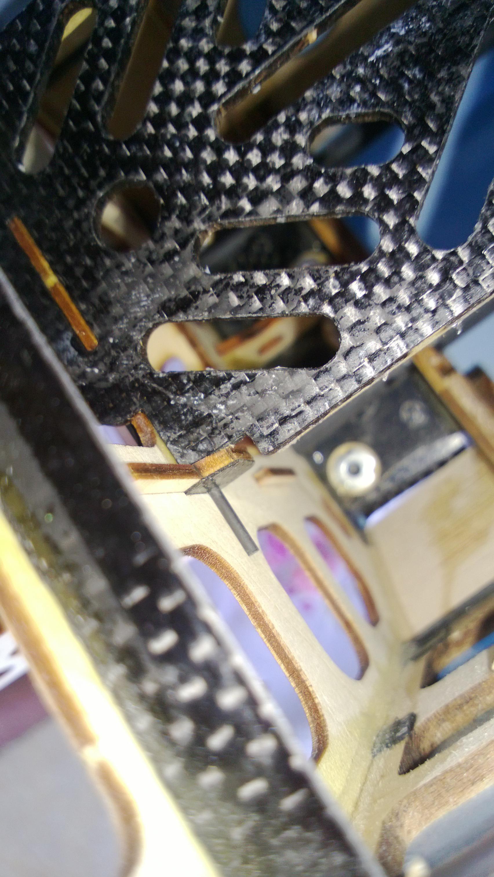
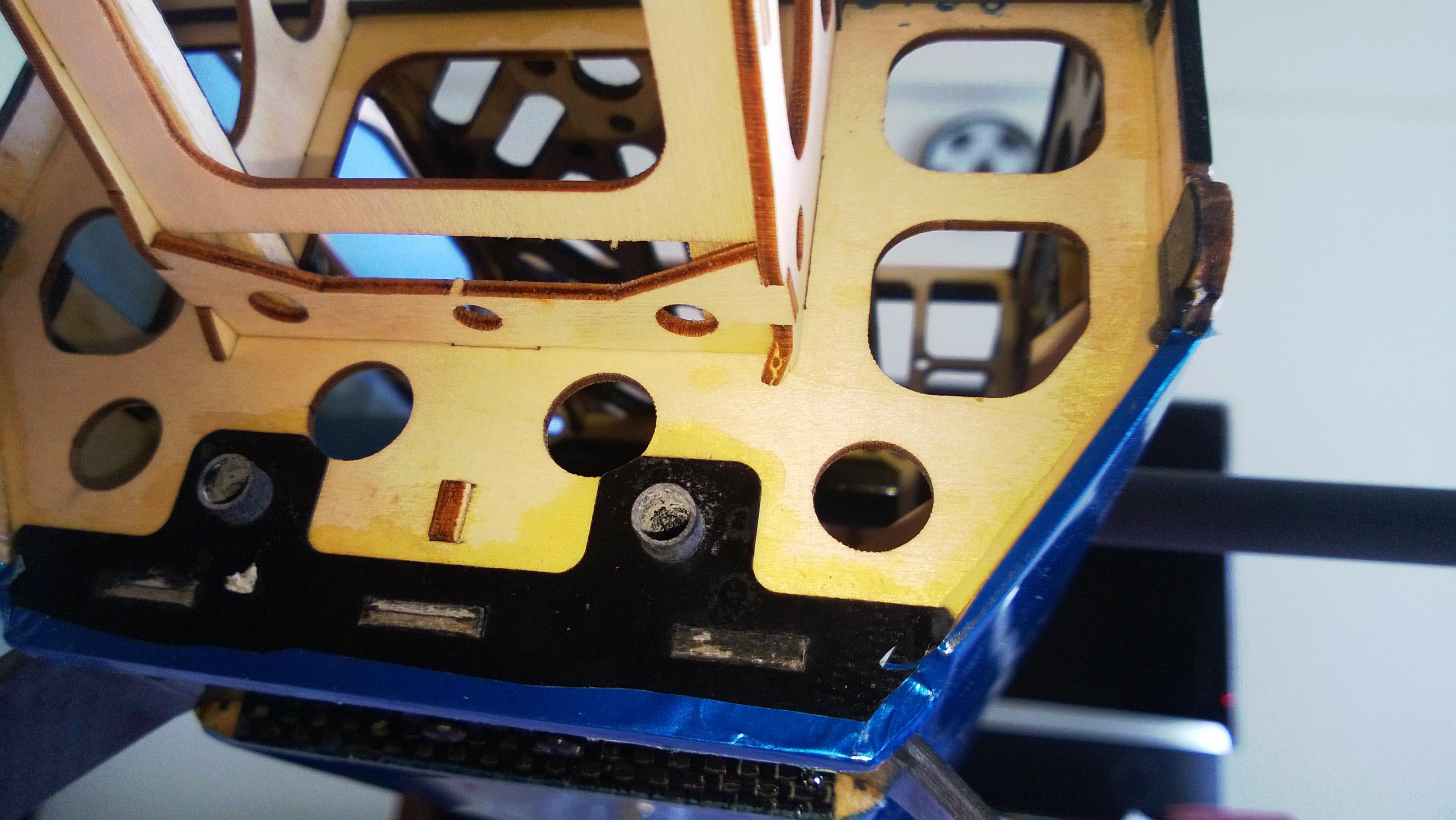
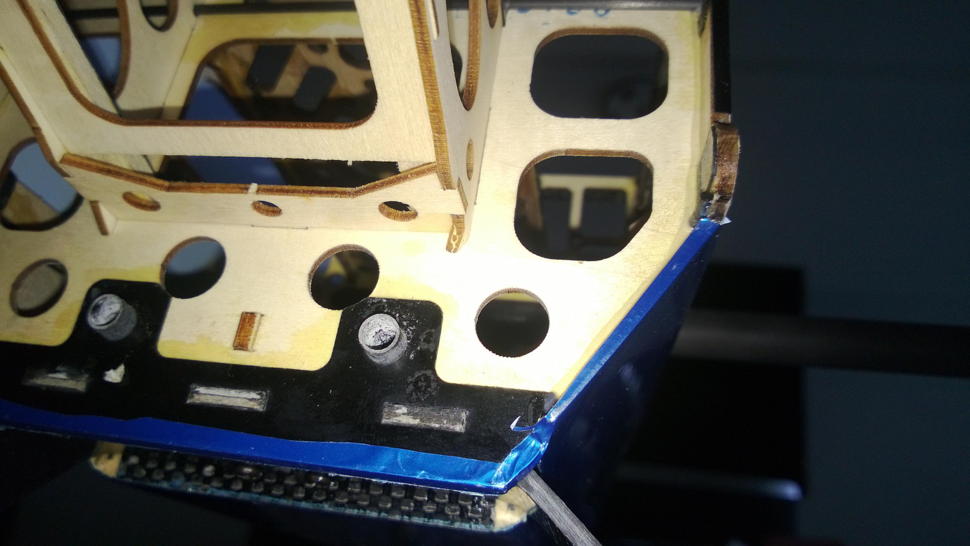
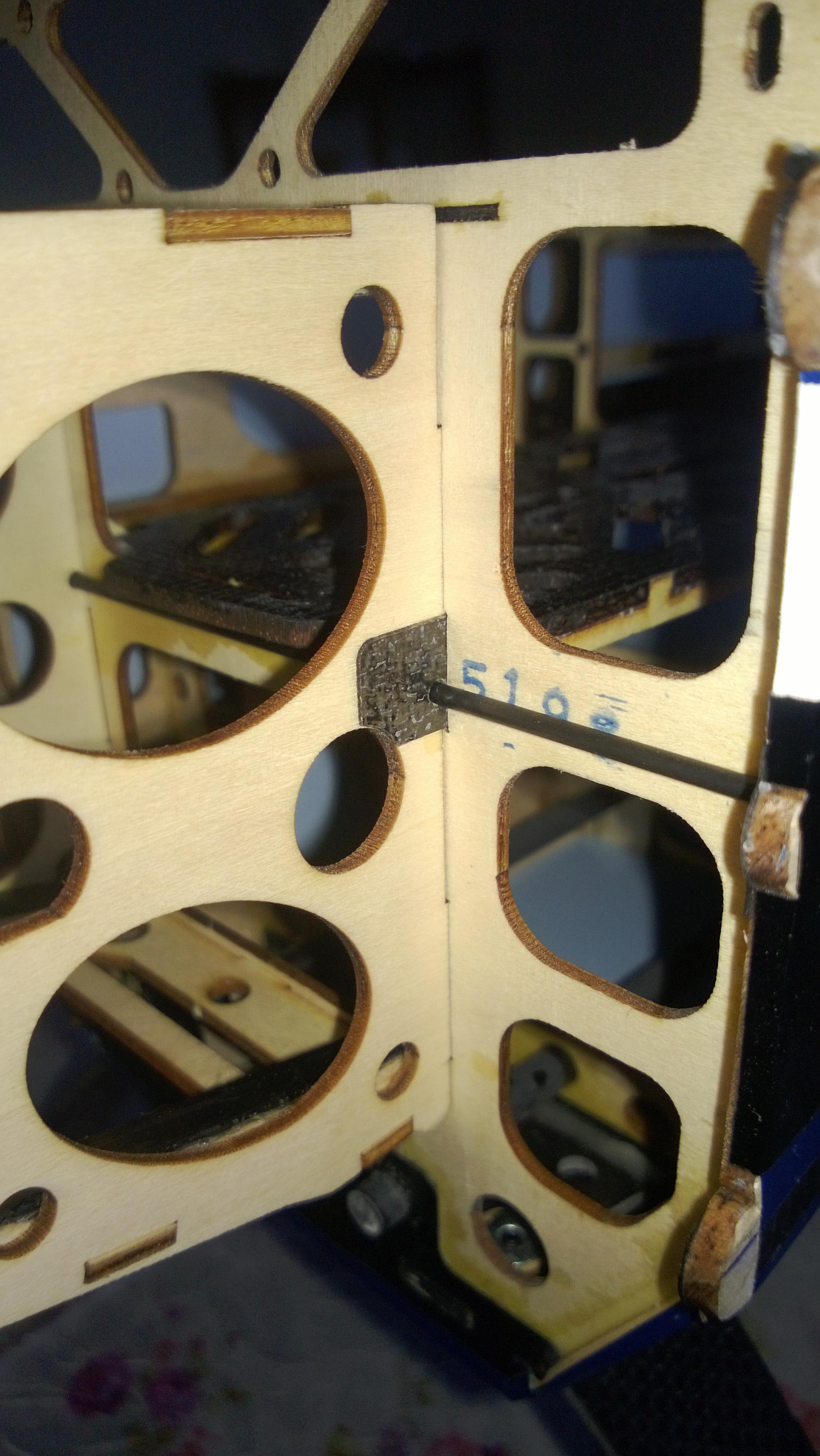
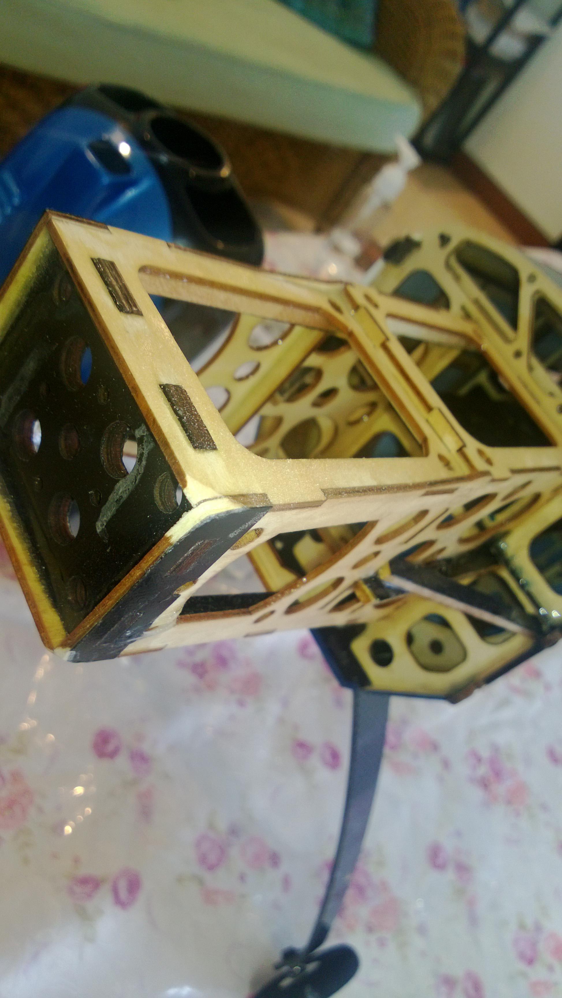
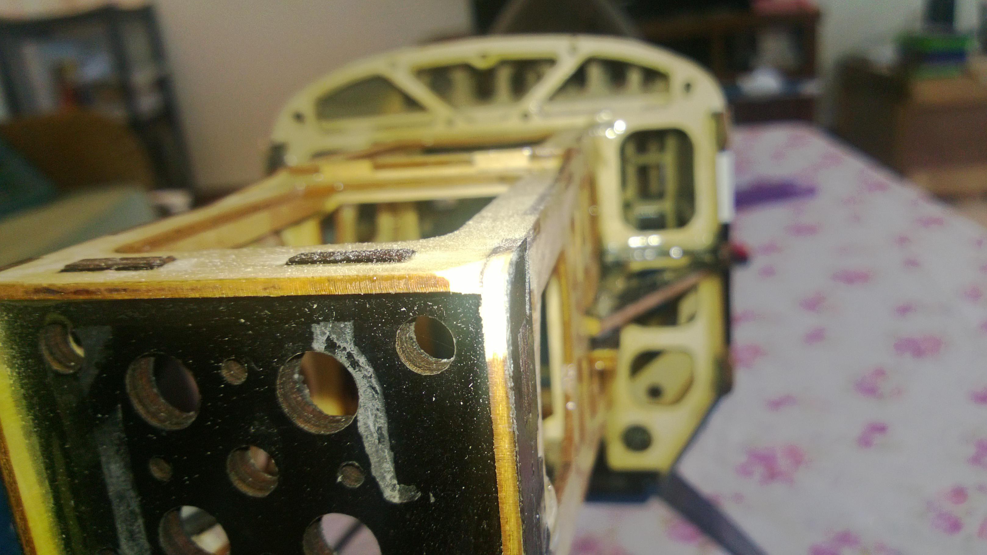
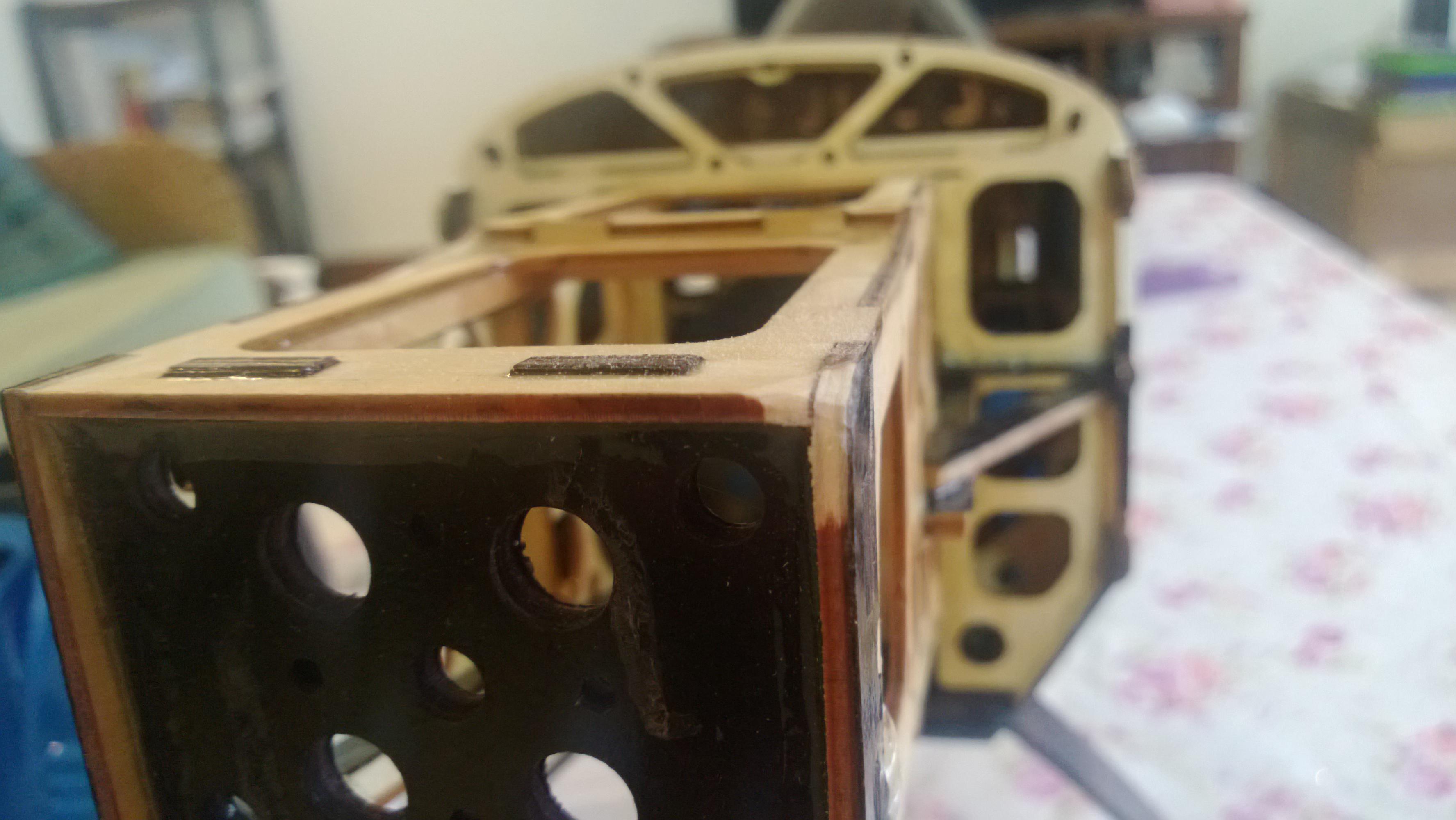
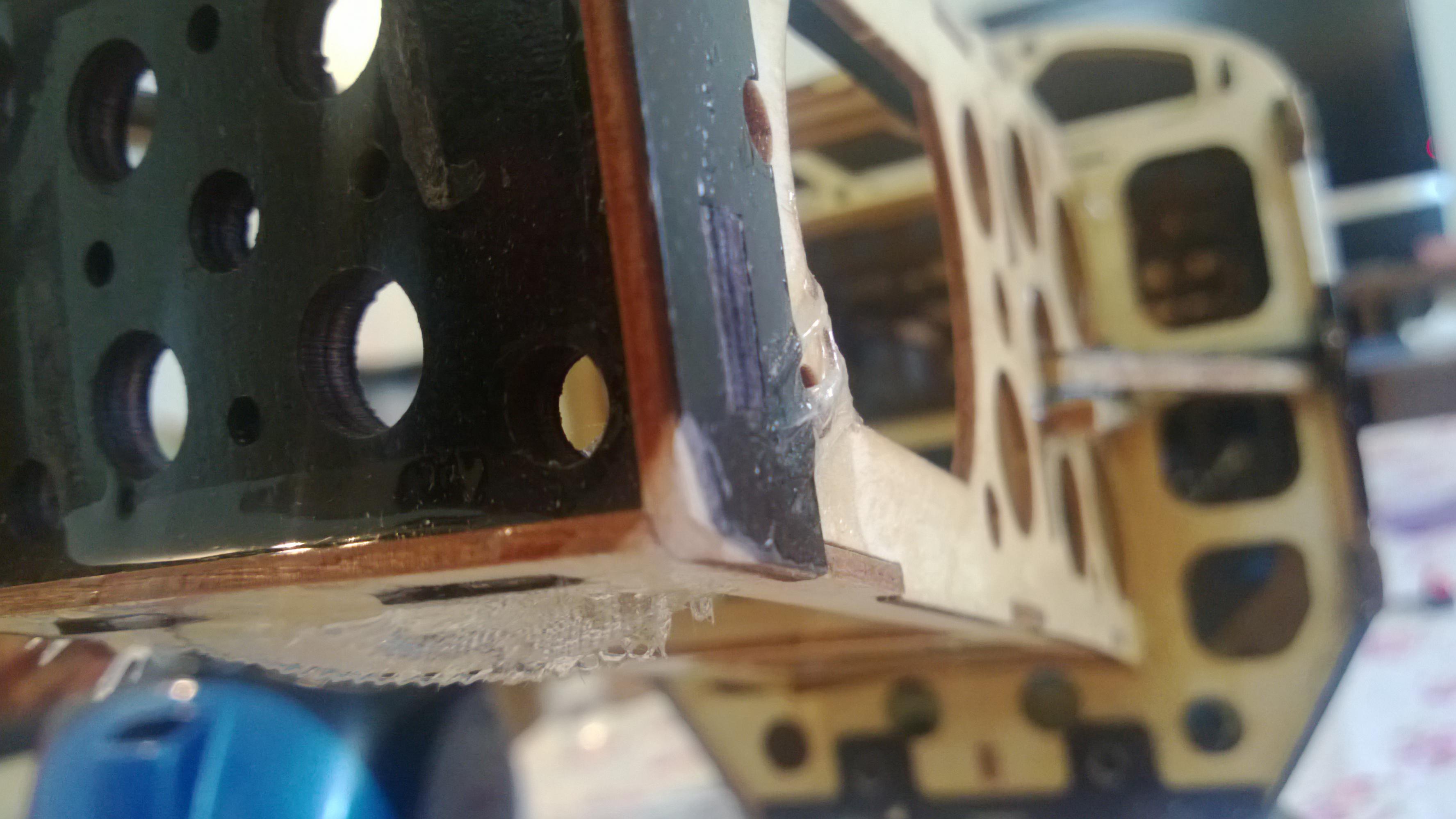
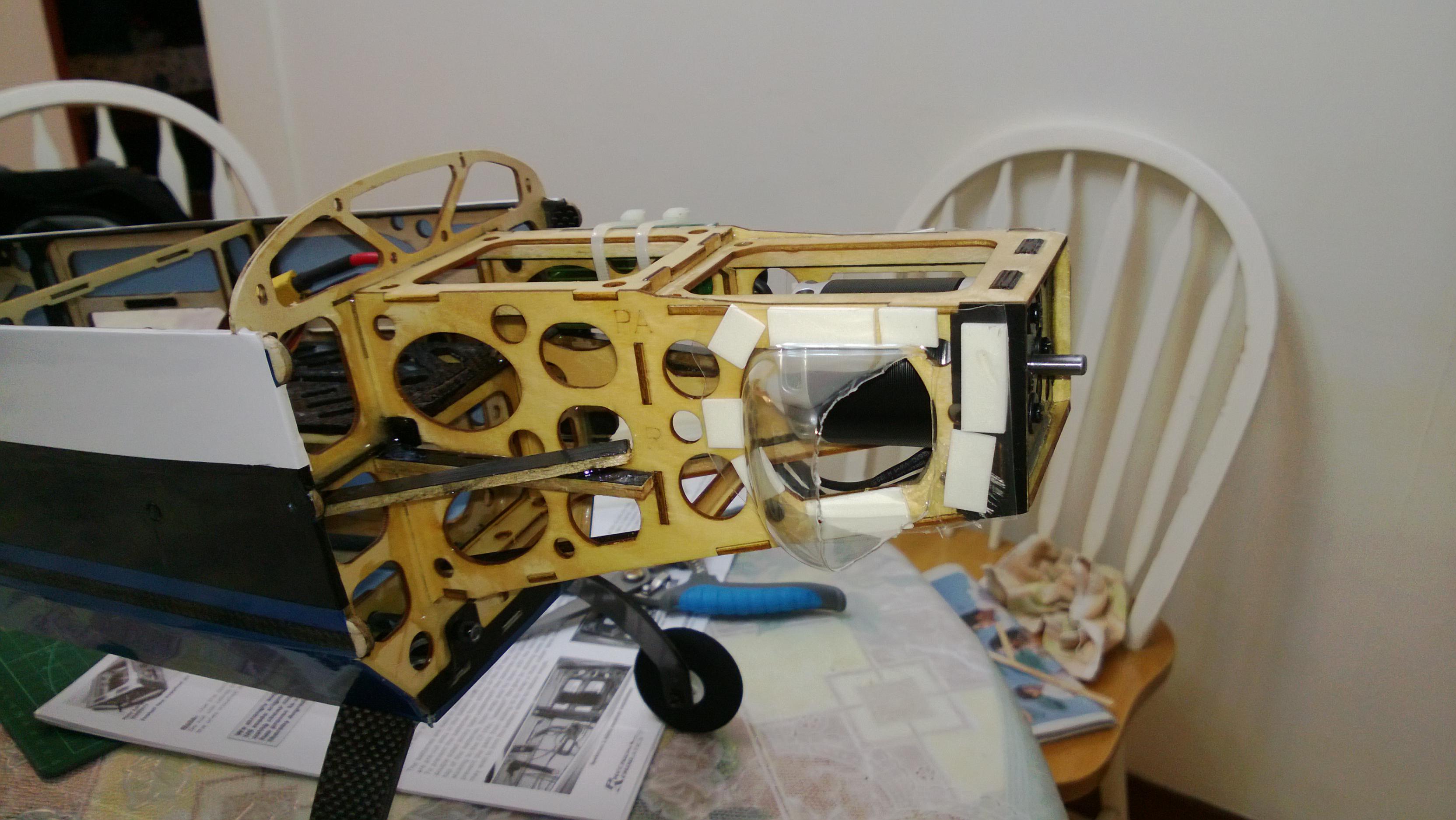
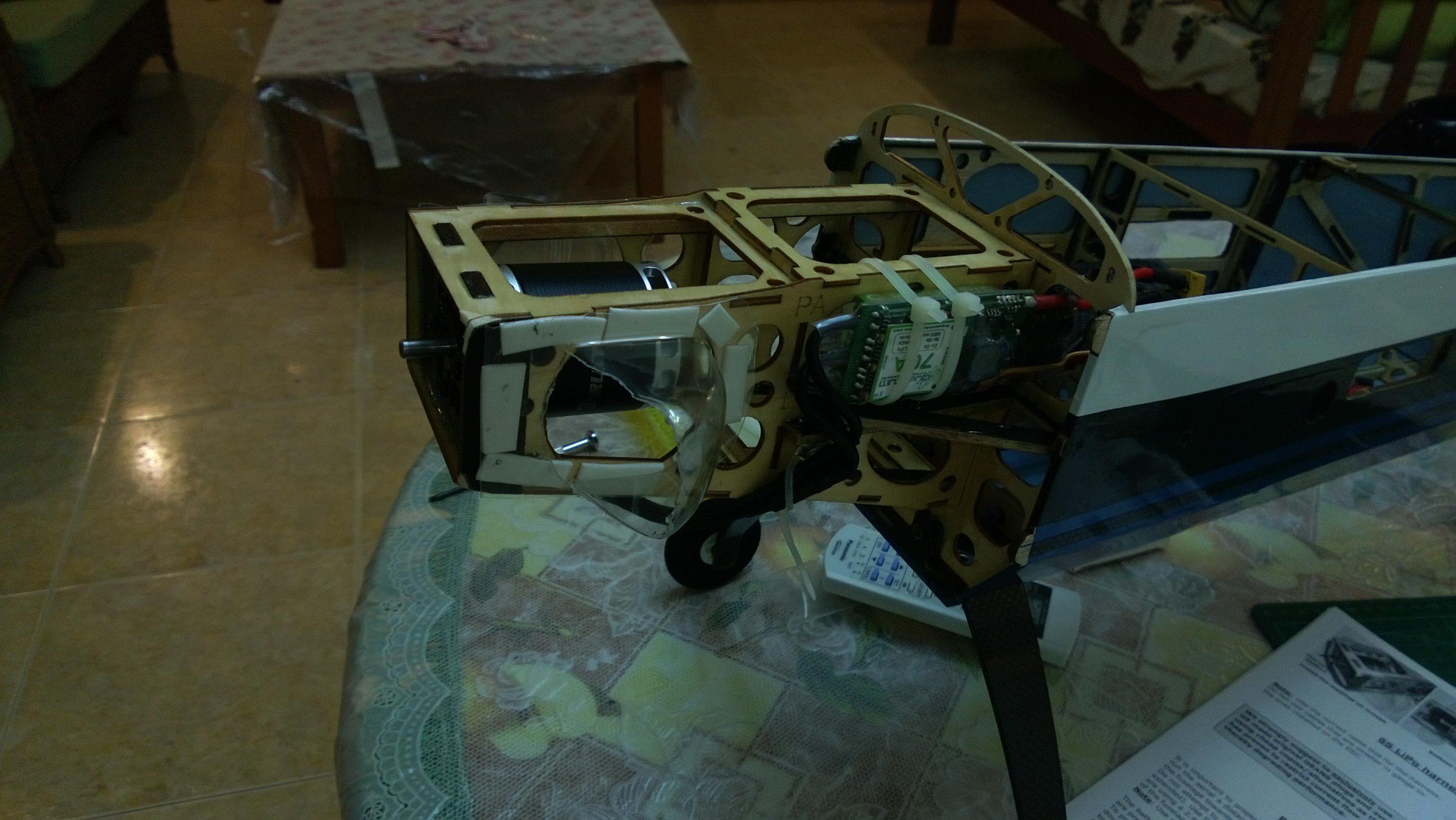
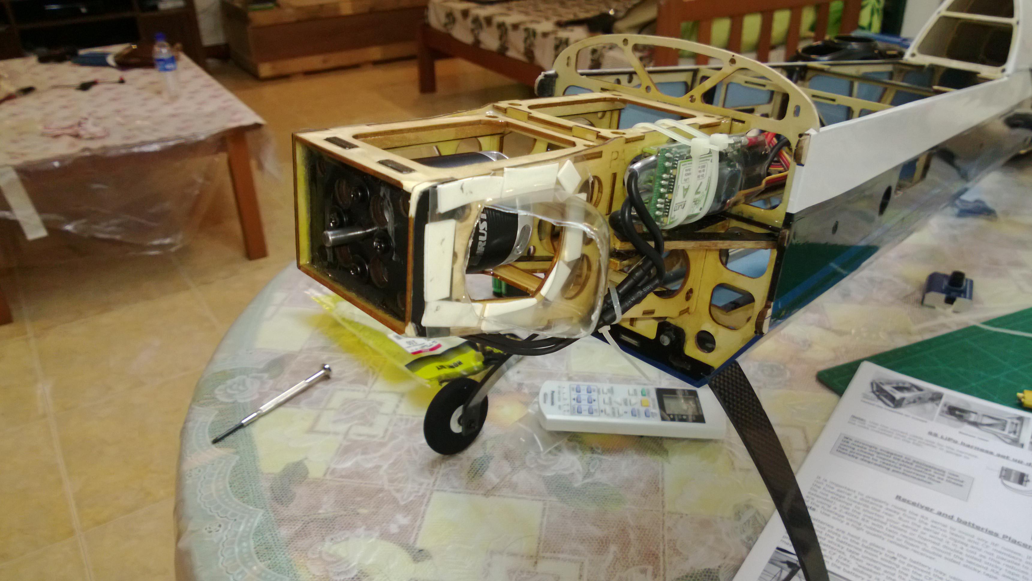
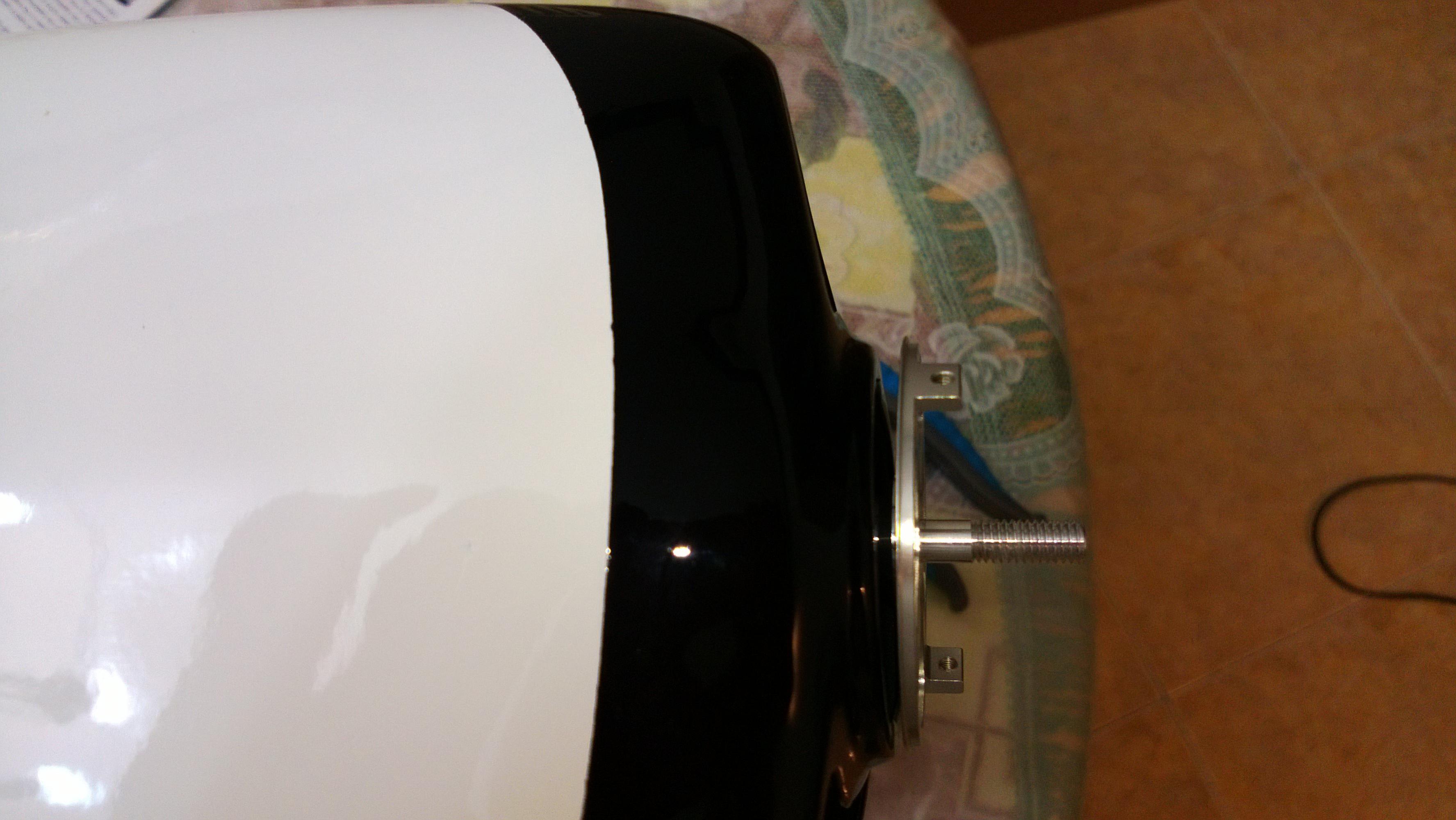
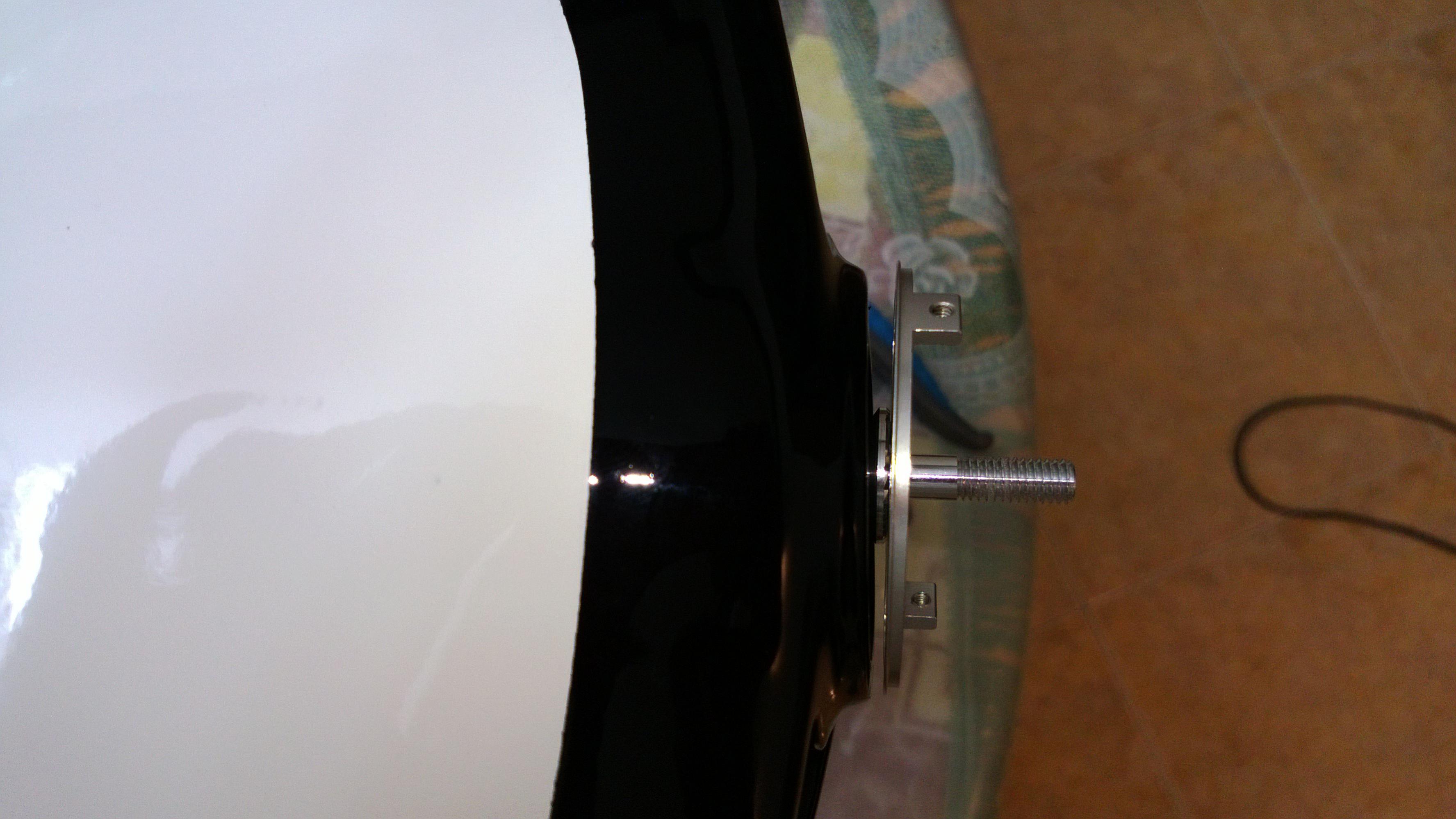
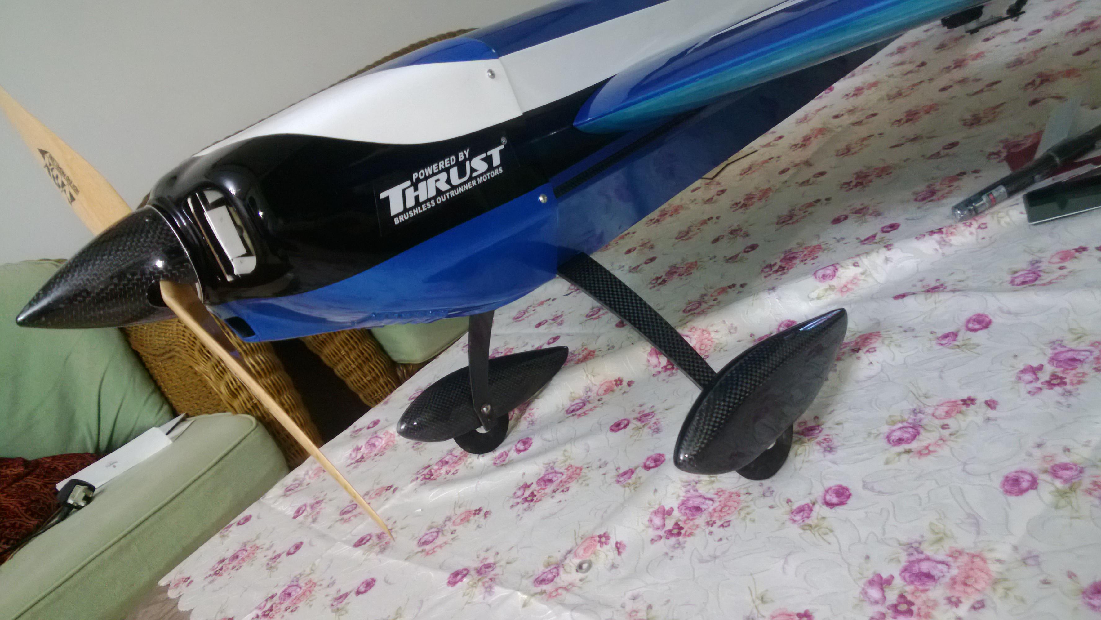
- Loved the alignment of the motor box it fits just right on. In my case the holes for the center CF rod were there I just needed to tap and open them up.
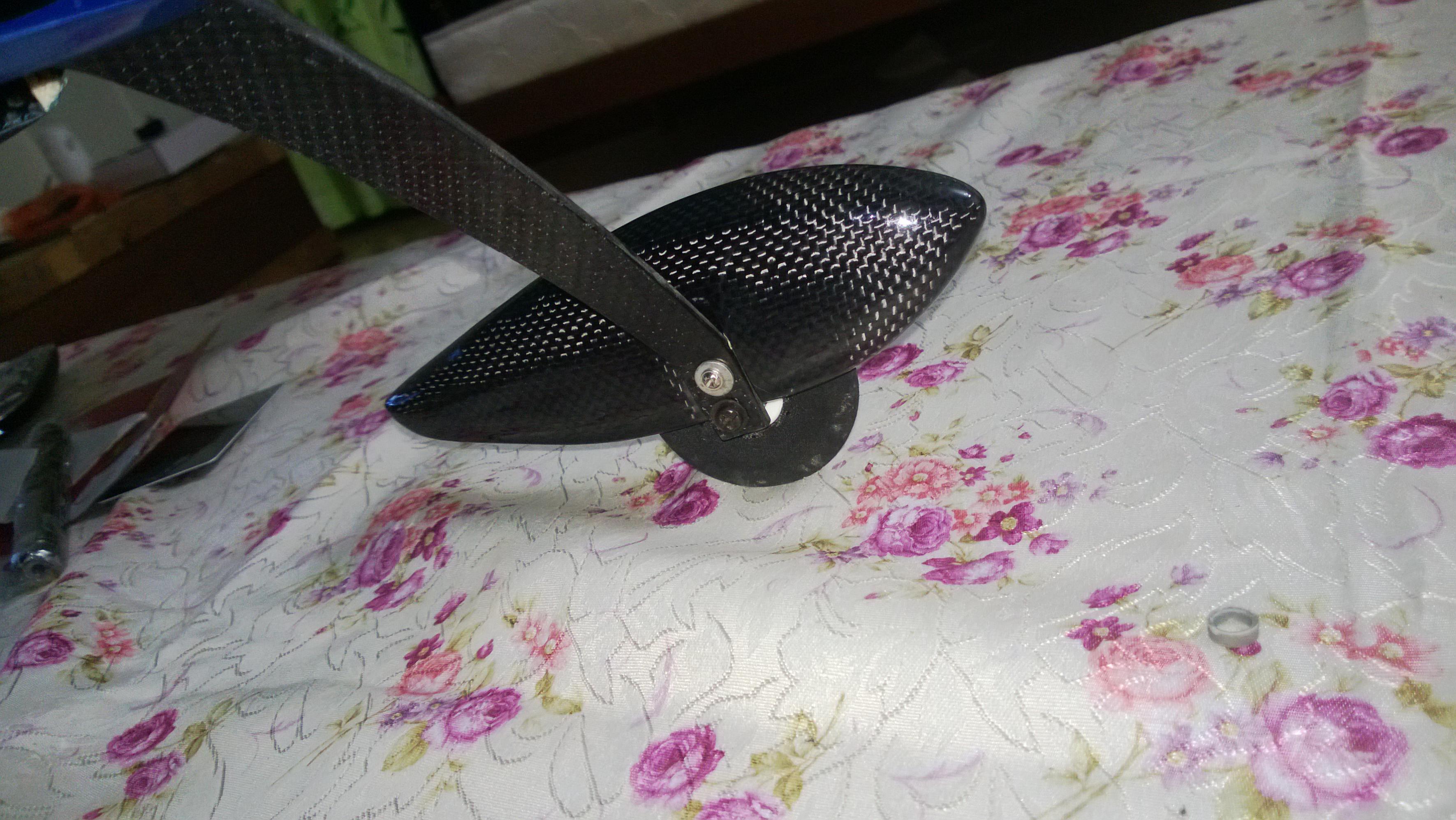
- The Landing gear Screws went right in without being a tight Fit at all and very easy loved the fitting unlike the KMD where the screws protruded out.
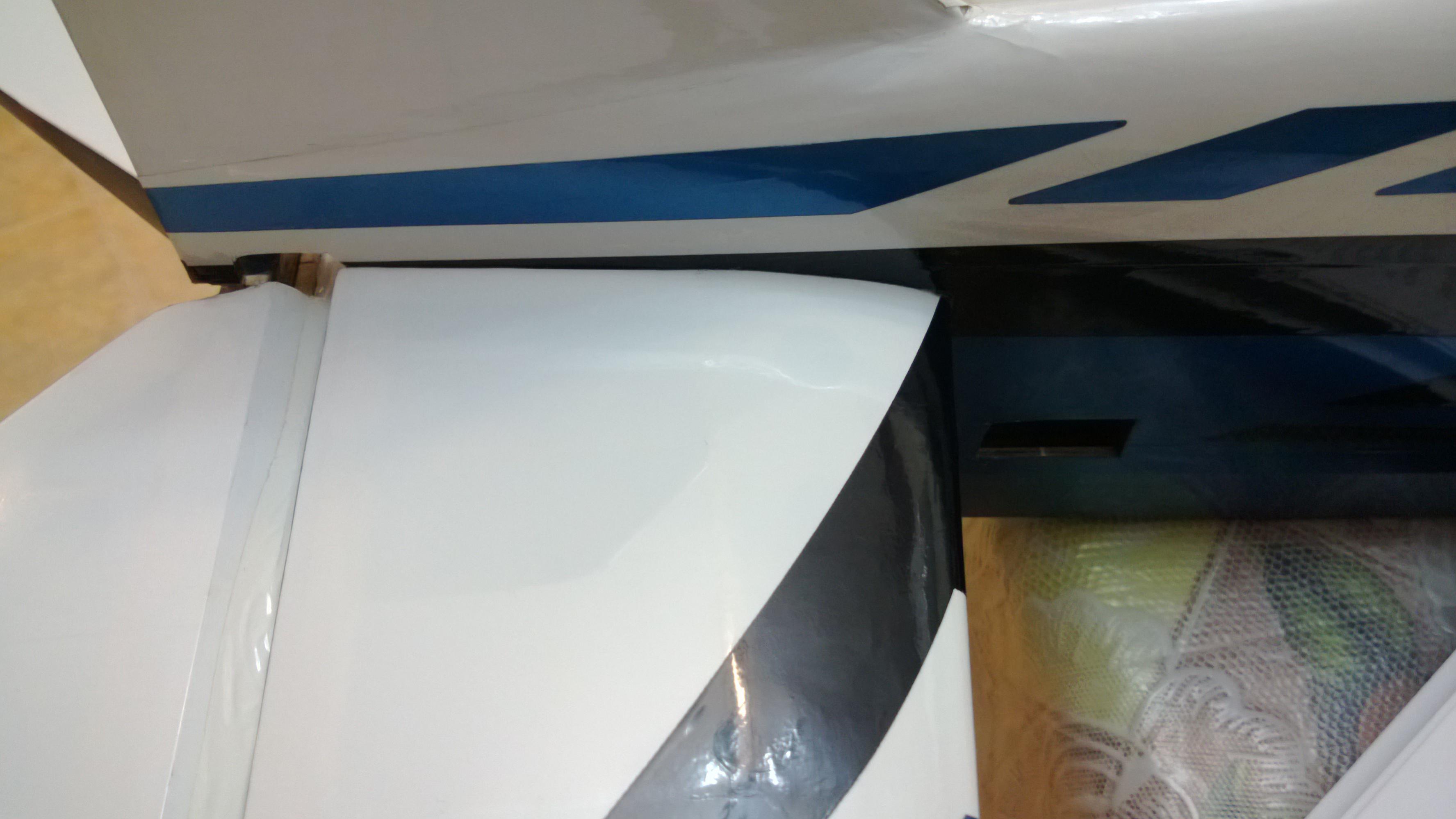
- The Rudder wheel base has been properly cut out and I jut had to cut the covering a bit surprisingly seemed like the marking for creating the hole for rudder wheels were in place.
- The wing CF rod went just right in without needing to be sanded.
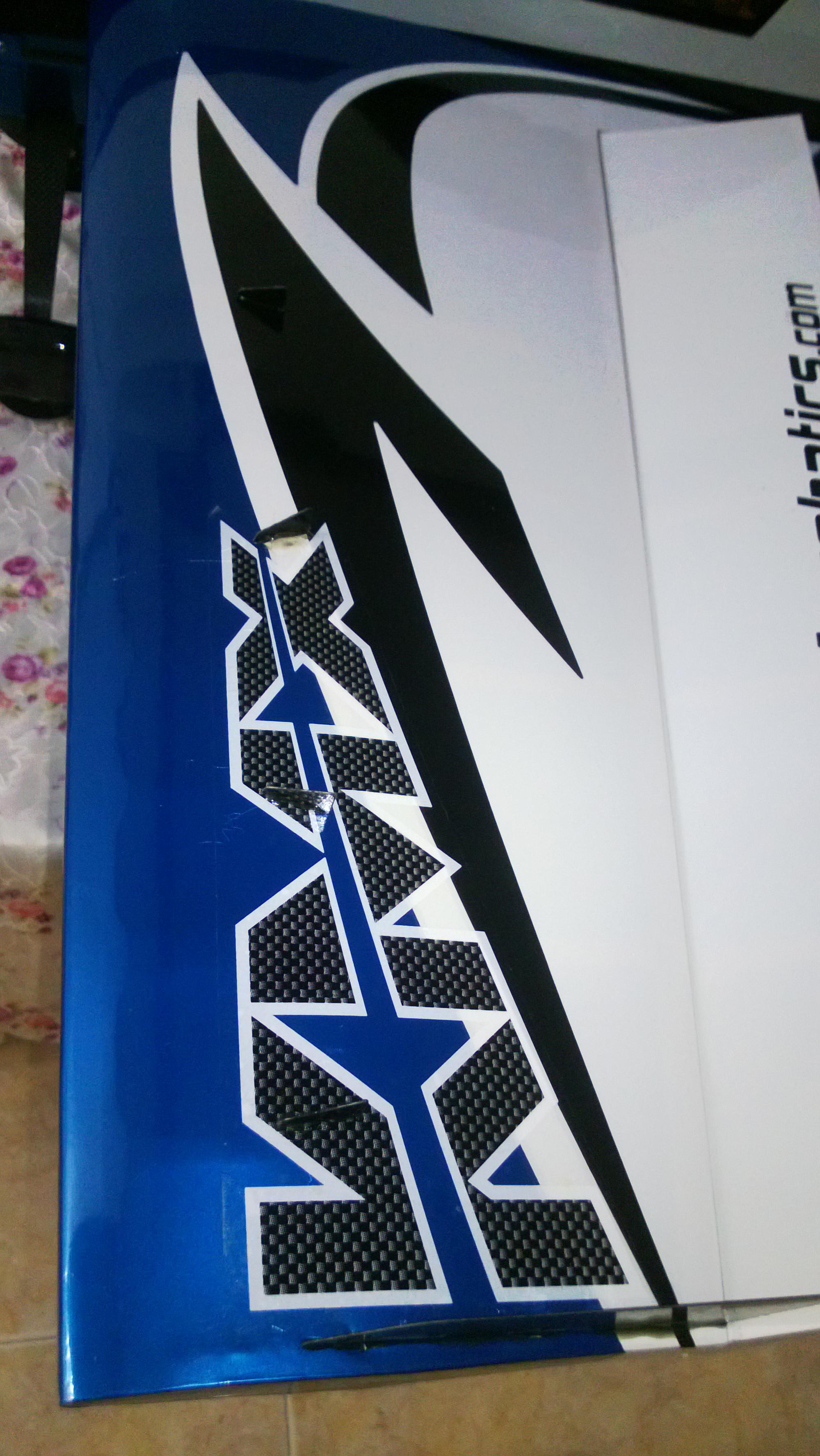
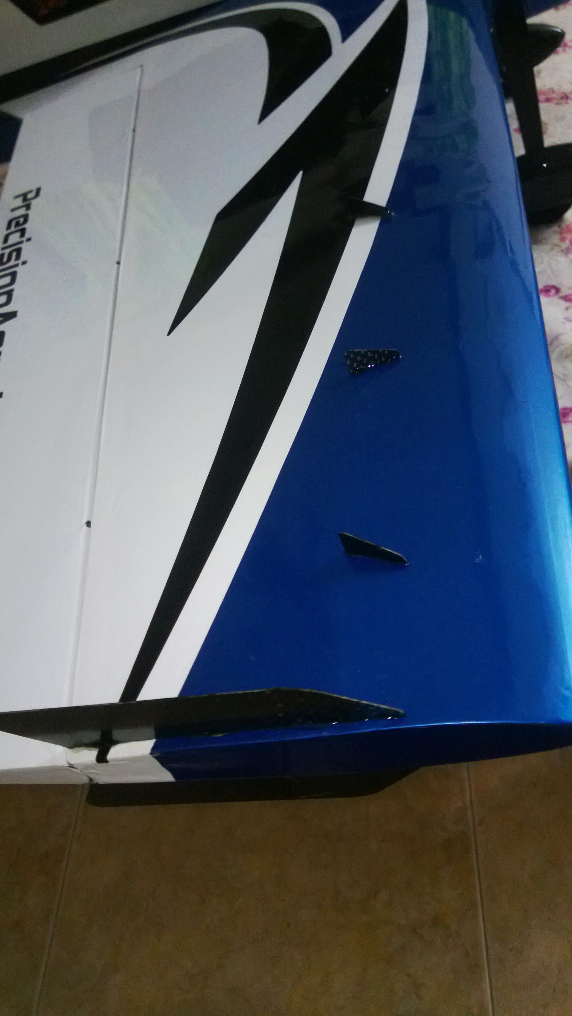
- Did not like the way the VG’s go in there, should be a better mechanism of getting the VG’s 1 out of the 3 VG’s did not line up the way. It was a little tricky to get them in place.
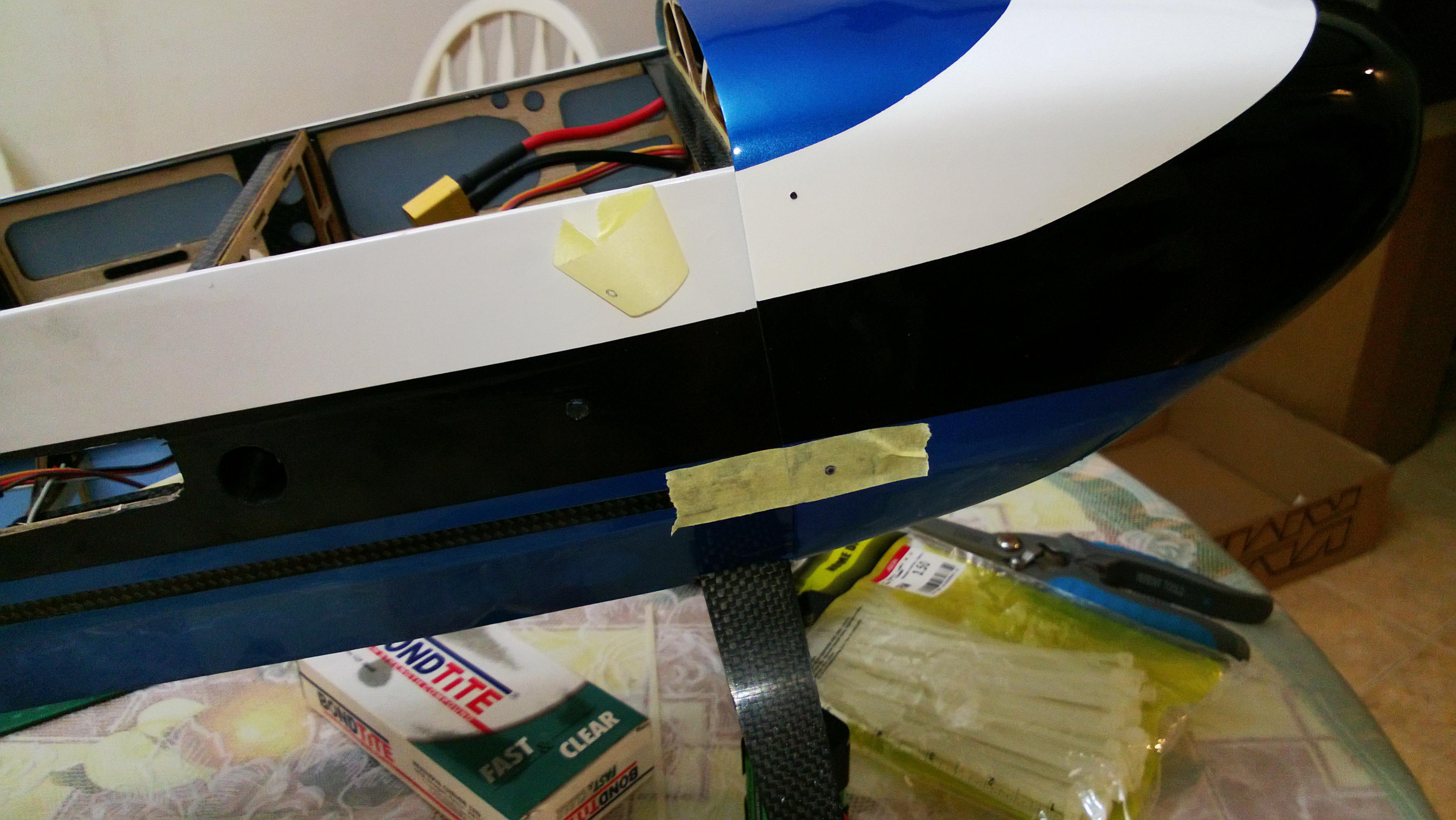
- The cowling seems to be a tight fit and took me quite some time to get it aligned, I guess one should spend a little bit more time to get this one right or may be it was just my piece.
- More to talk about as we move on keep reading .....
.....
The rest of the Fiber fusion is just perfect on the spot like other Models.
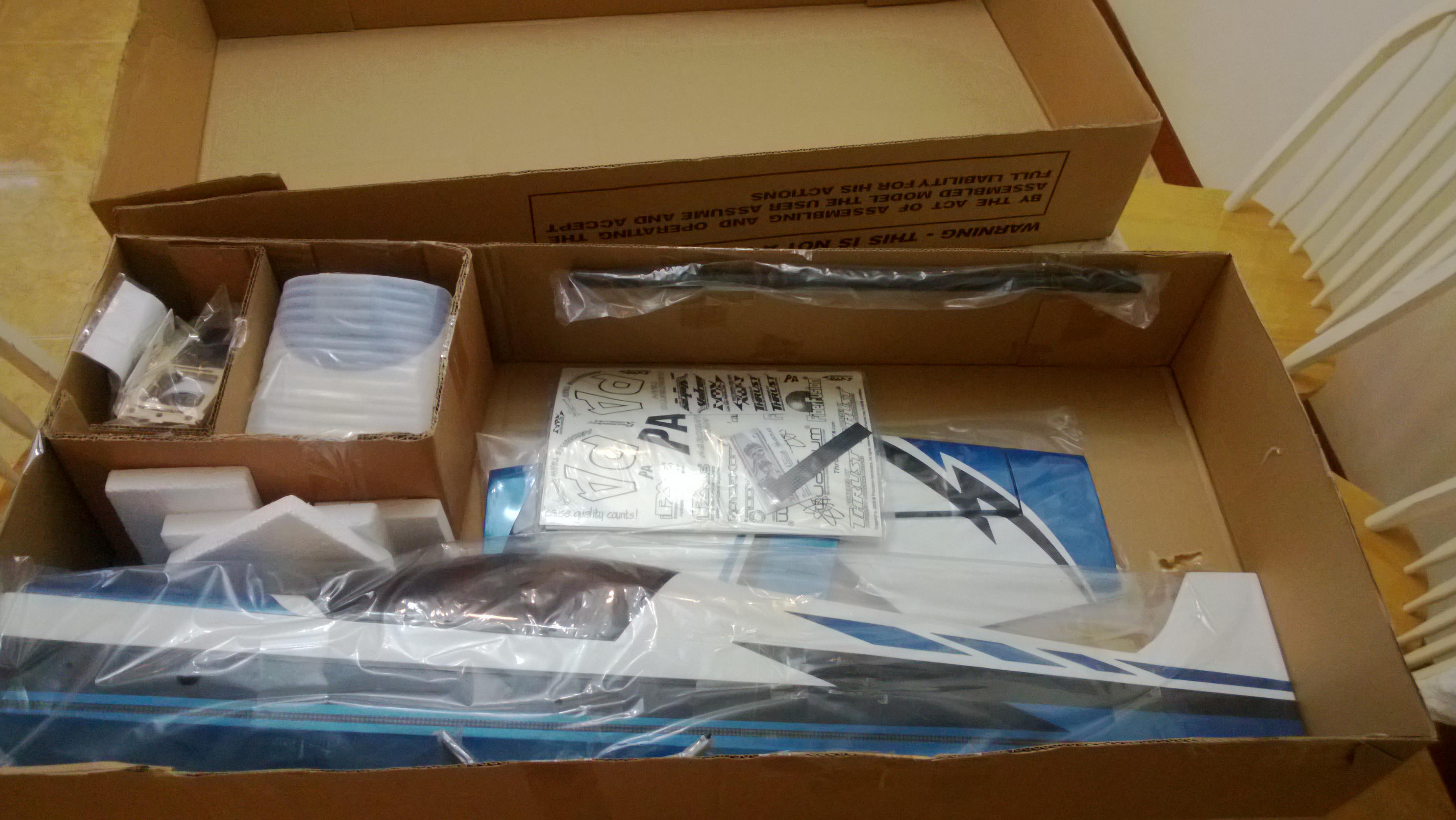
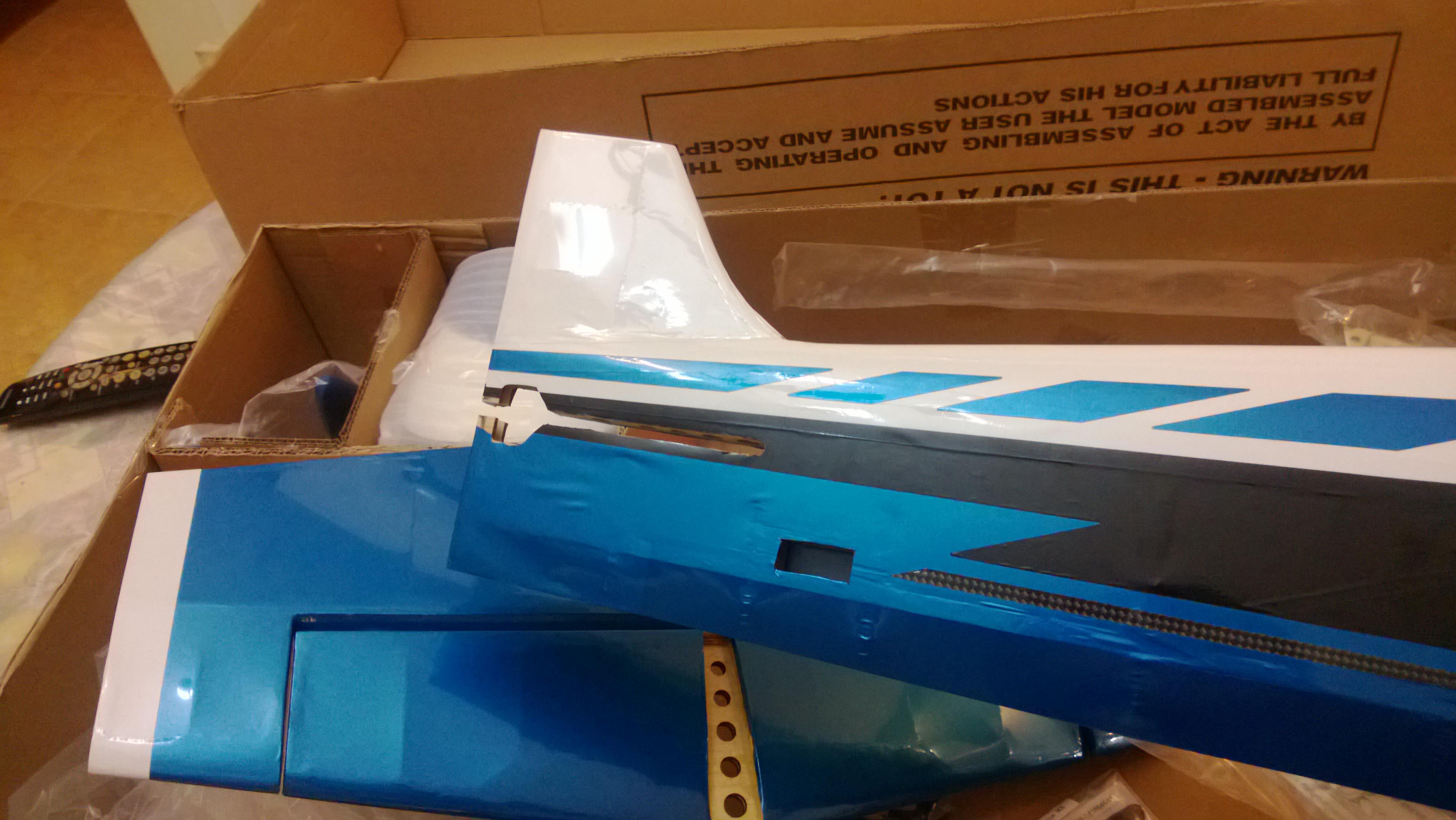
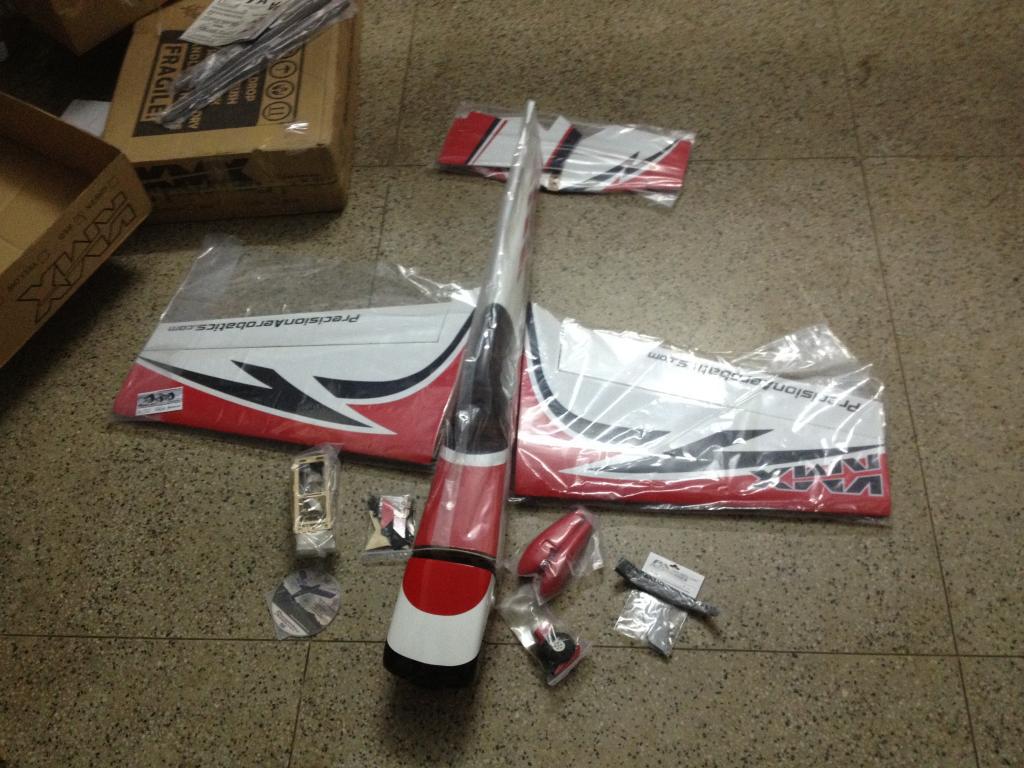
Here we Go, The box should look something like the below pic , I opted for the Blue one as the color Scheme and visibility is Just Brilliant.

There is a nice video of what you can expect in the package, here.
My Pic does not show the Wings they were outside the box , But you will see them soon.
I followed the manual Completely and i recommend any one who is starting the build to first go through the manual thoroughly, You will not repent that you spent the extra time reading this manual. it is very thorough and nicely written. 1.)
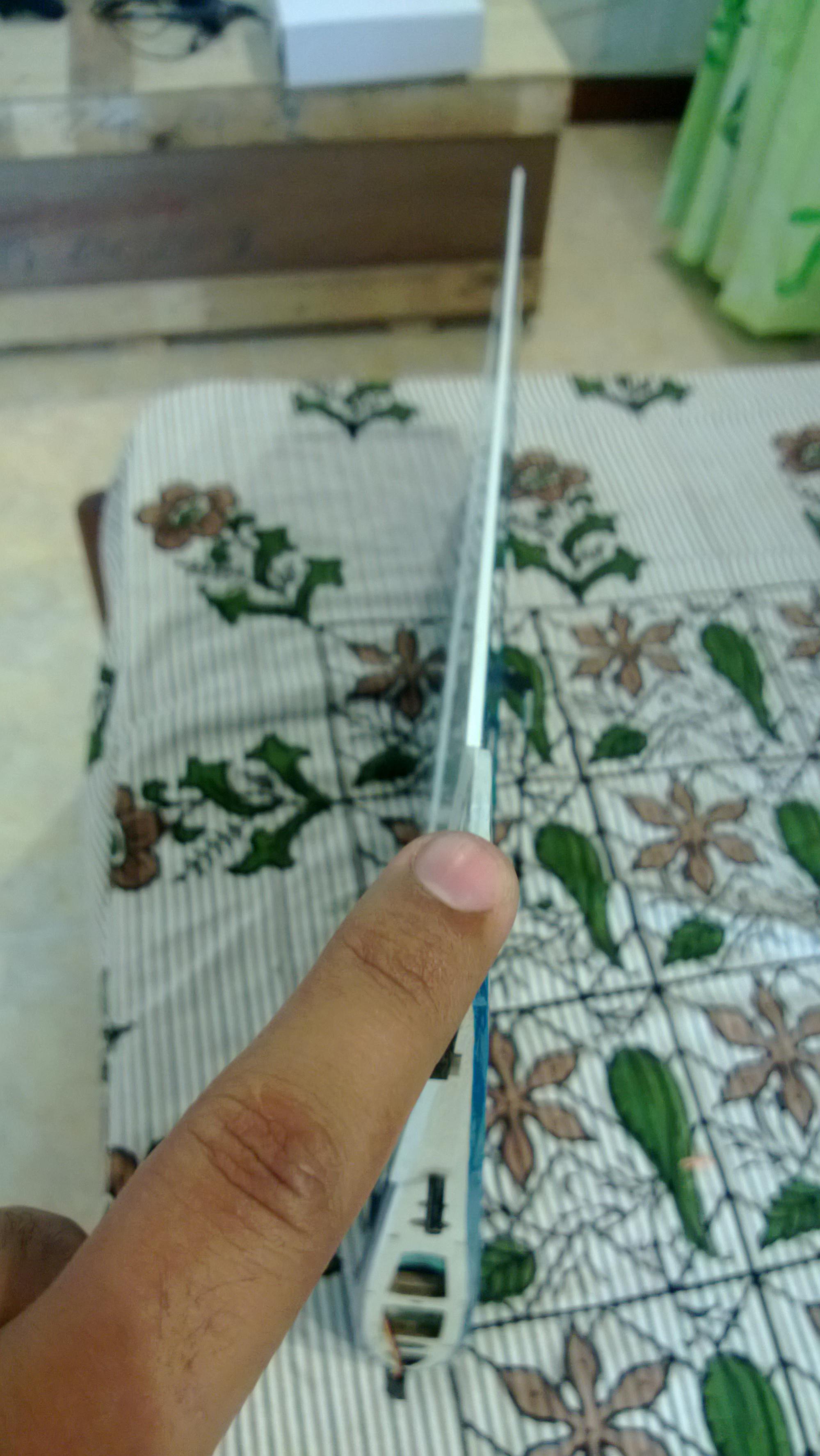
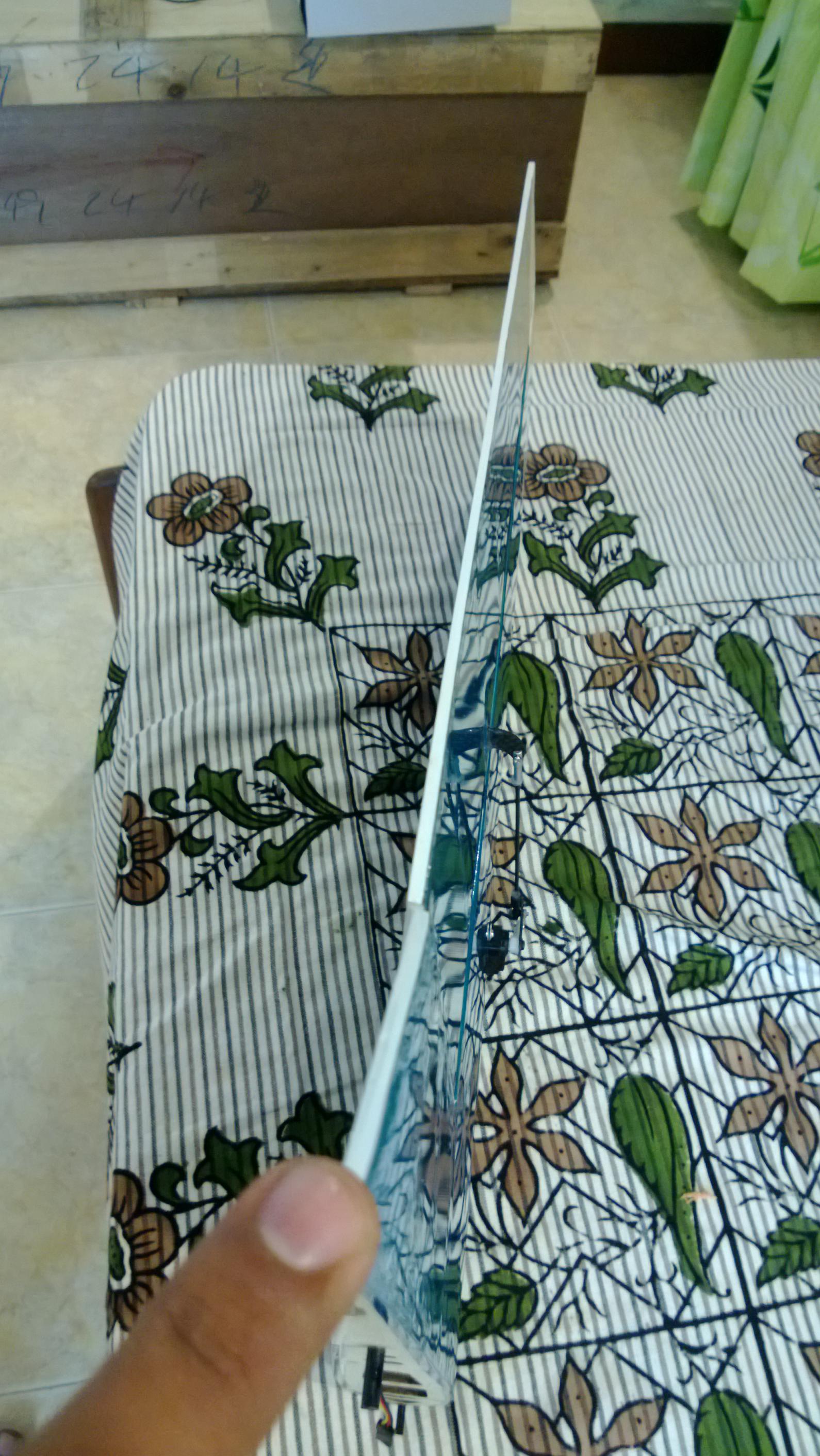
1. Start by Cutting the Coverings as suggested in the manual
I did the Servo bays in the wings and the rest of the fuselage.
[BTIP:- If you use the hot paper clip mentioned in the manual you will get a very nice clean cut, Since i did not have the paper clip i used my Hobby Xacto Knife and heated the tip of the knife for doing the cuts the result is seen below [/B]


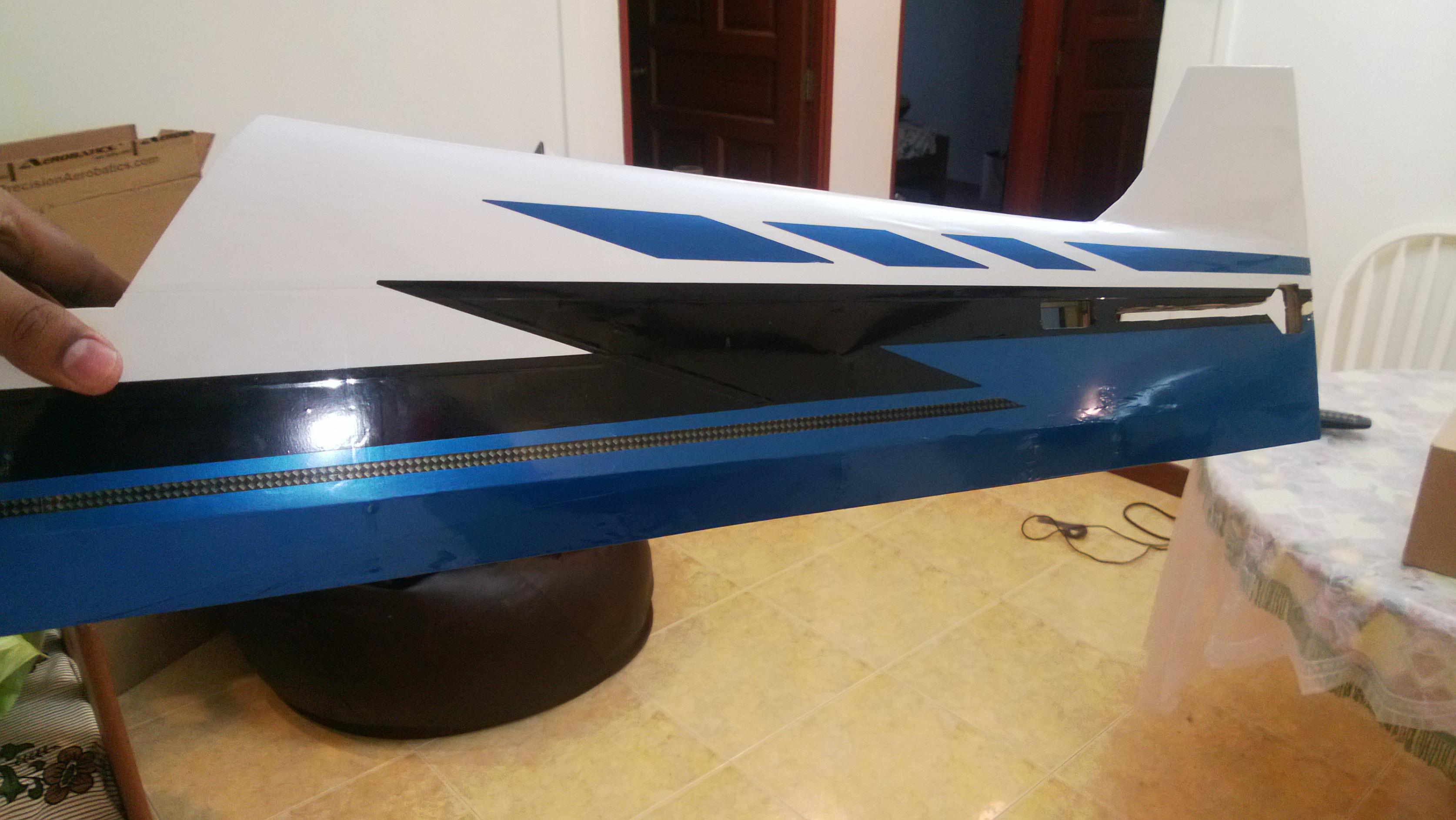
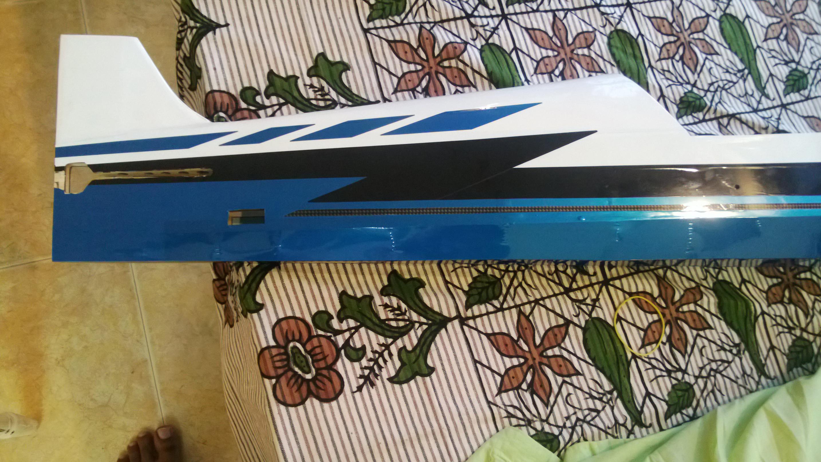
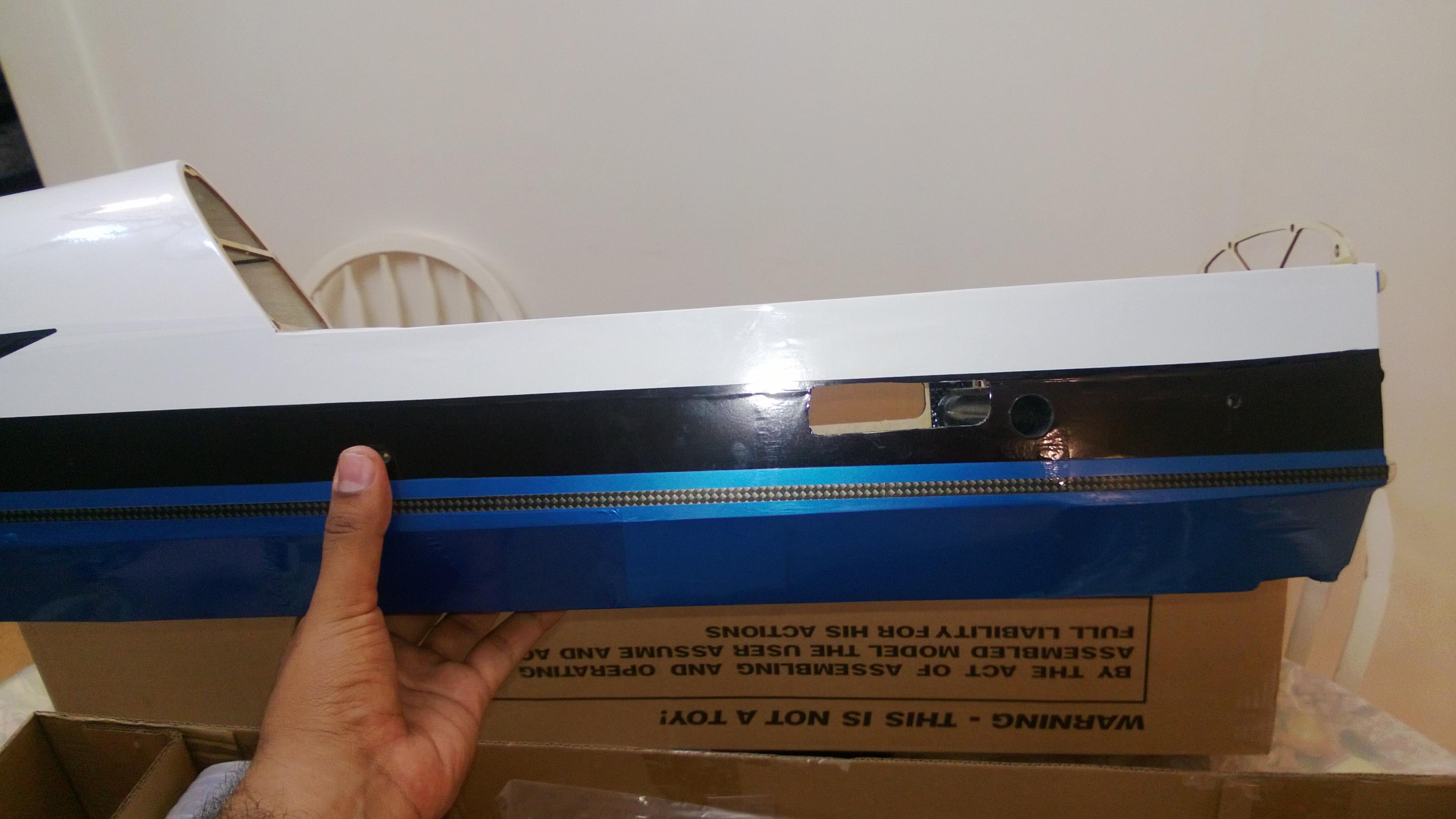
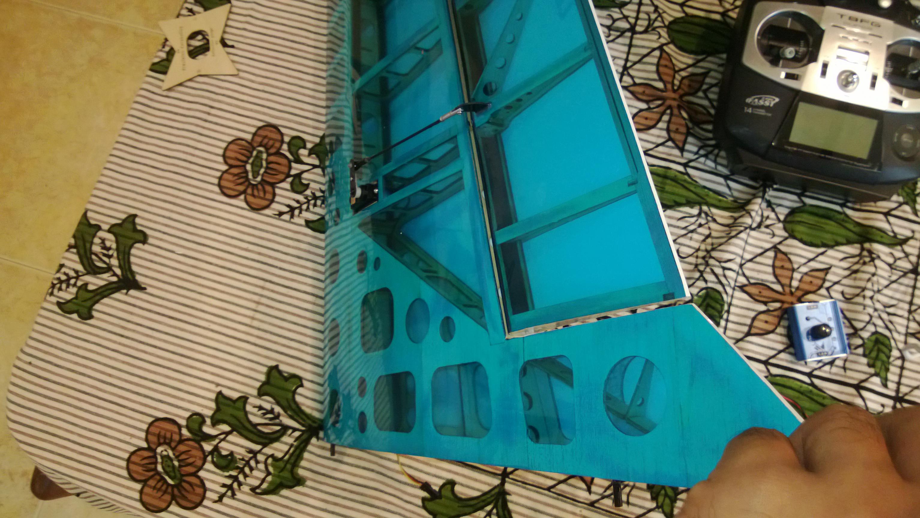
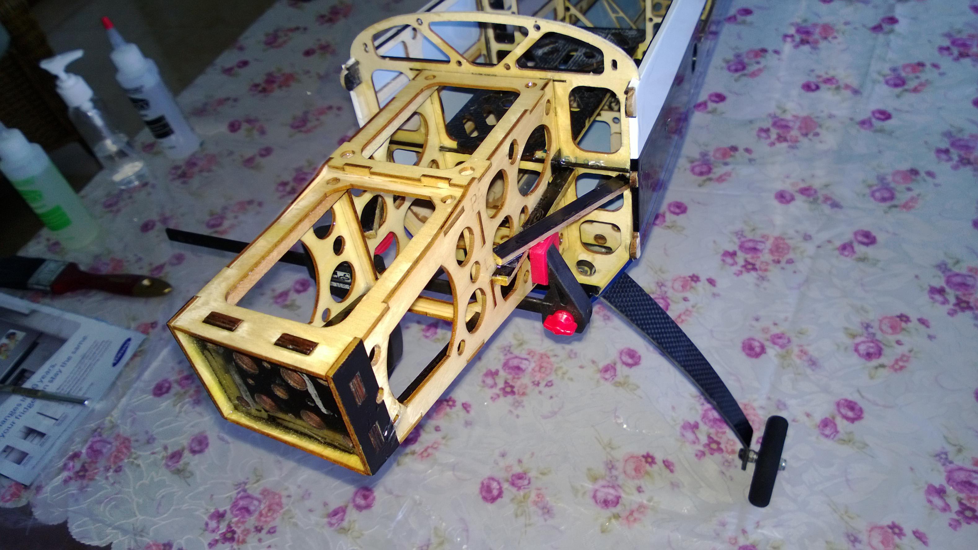
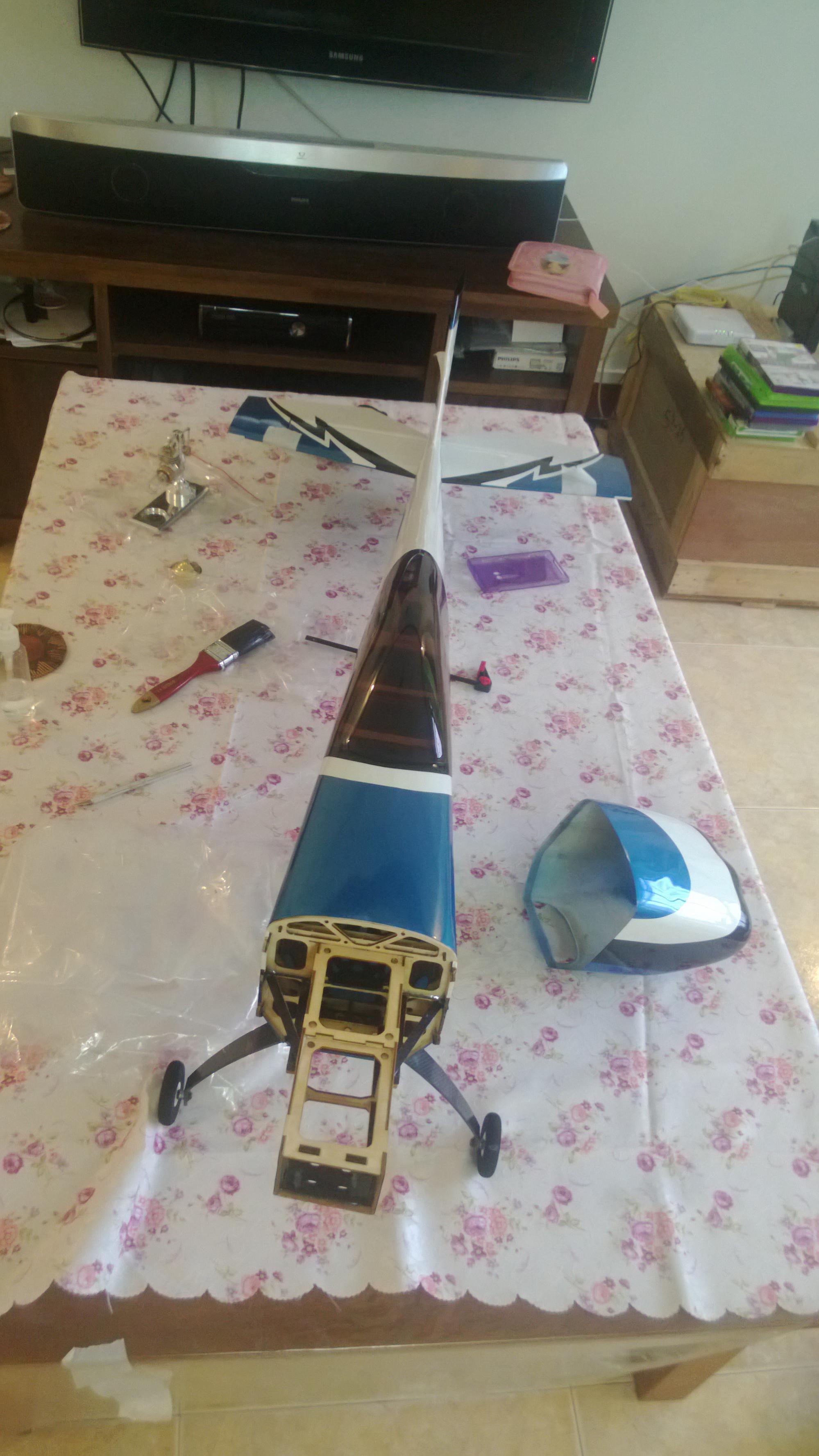
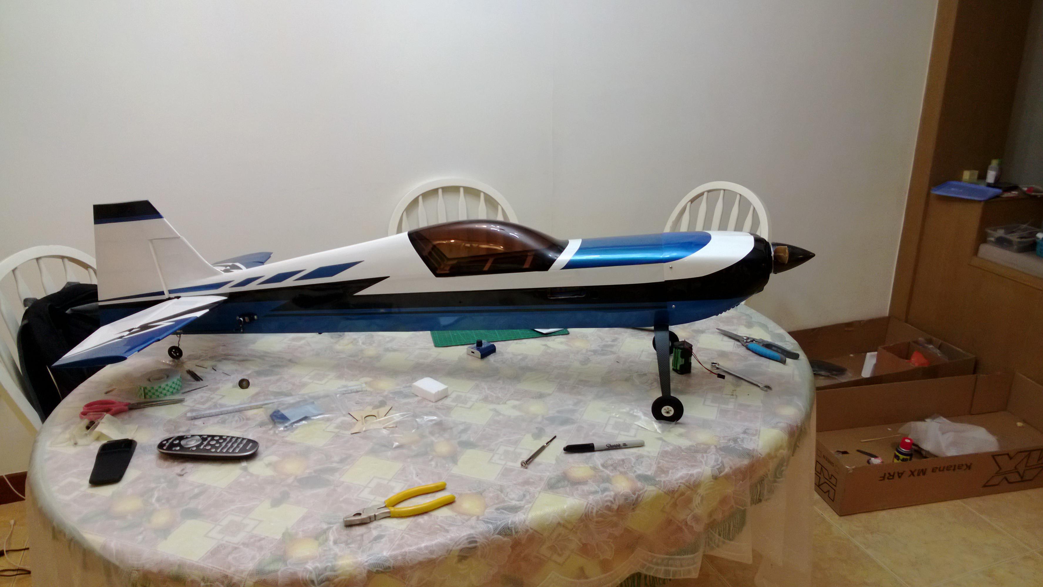
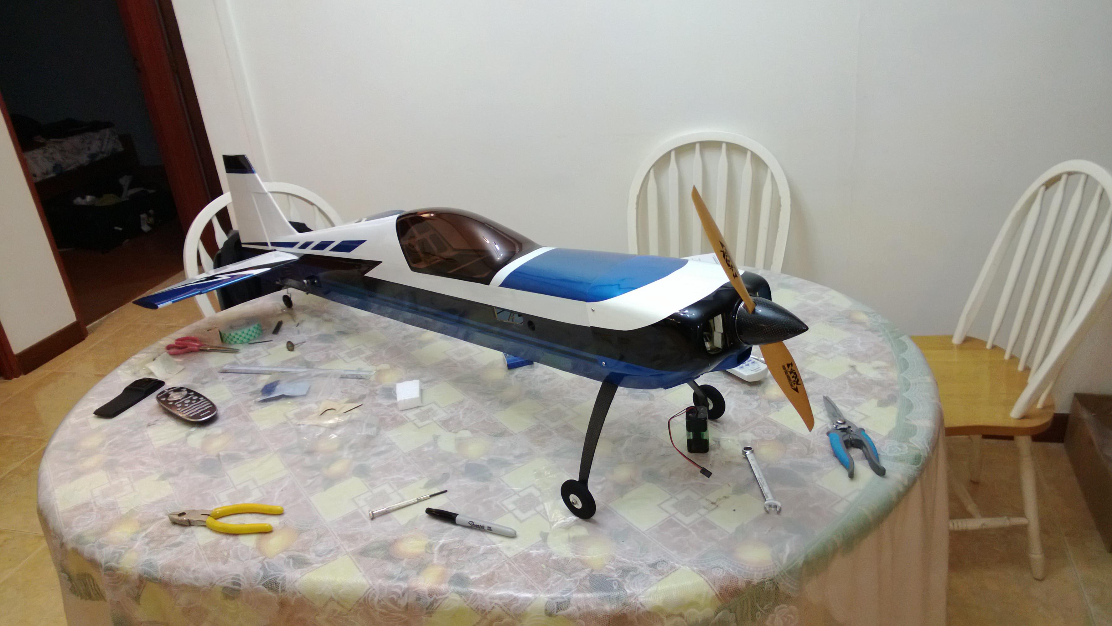
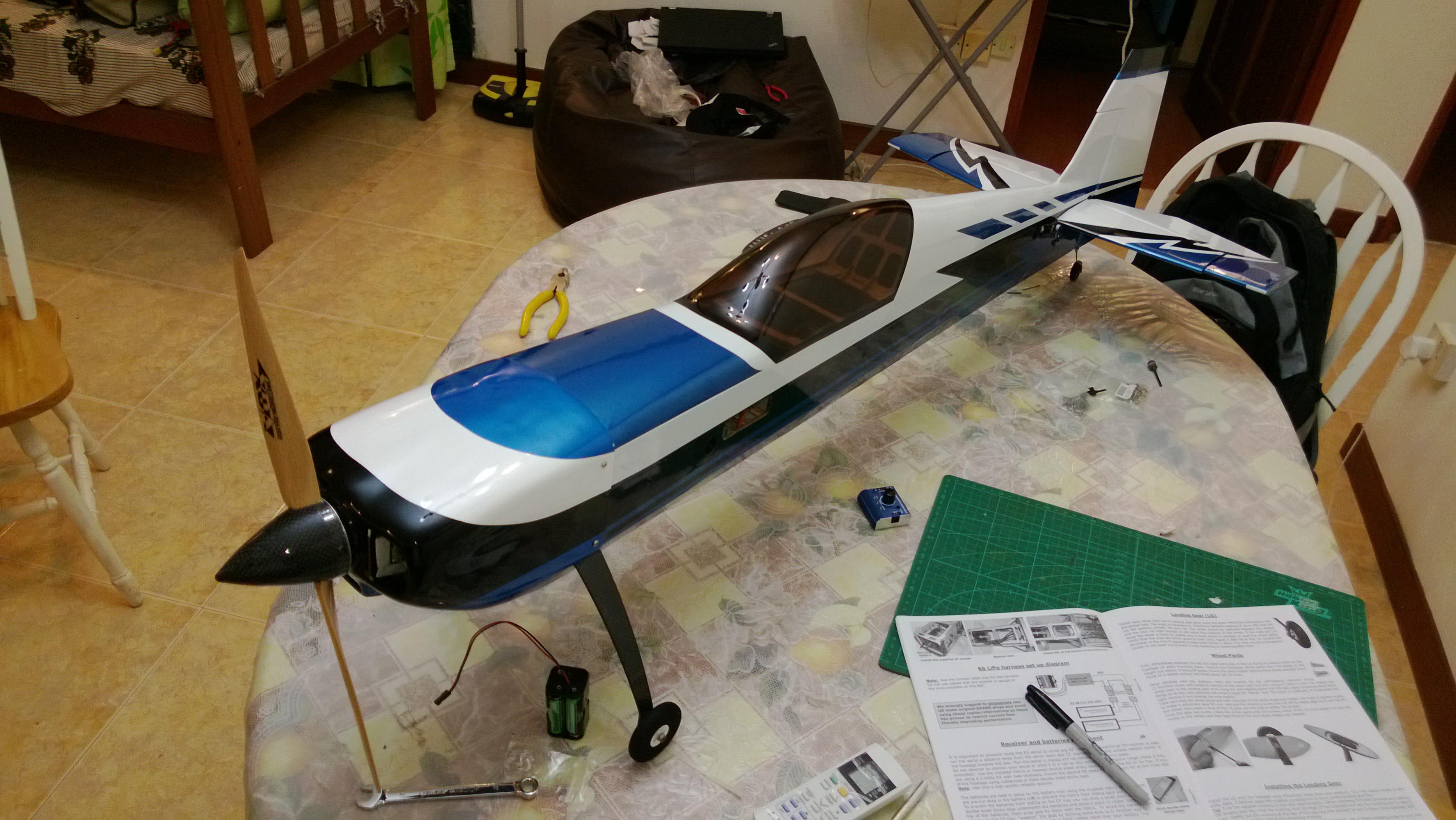
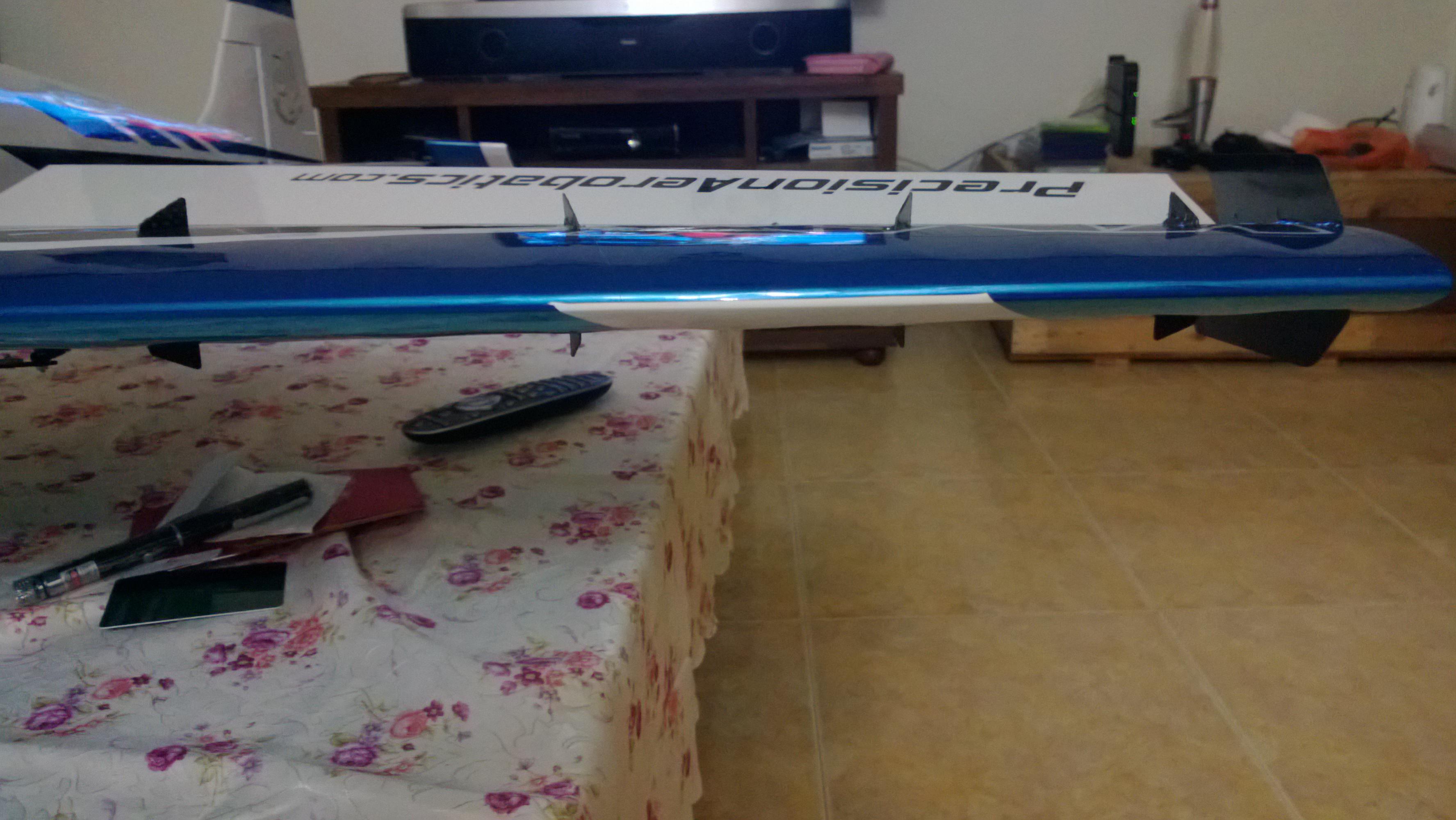
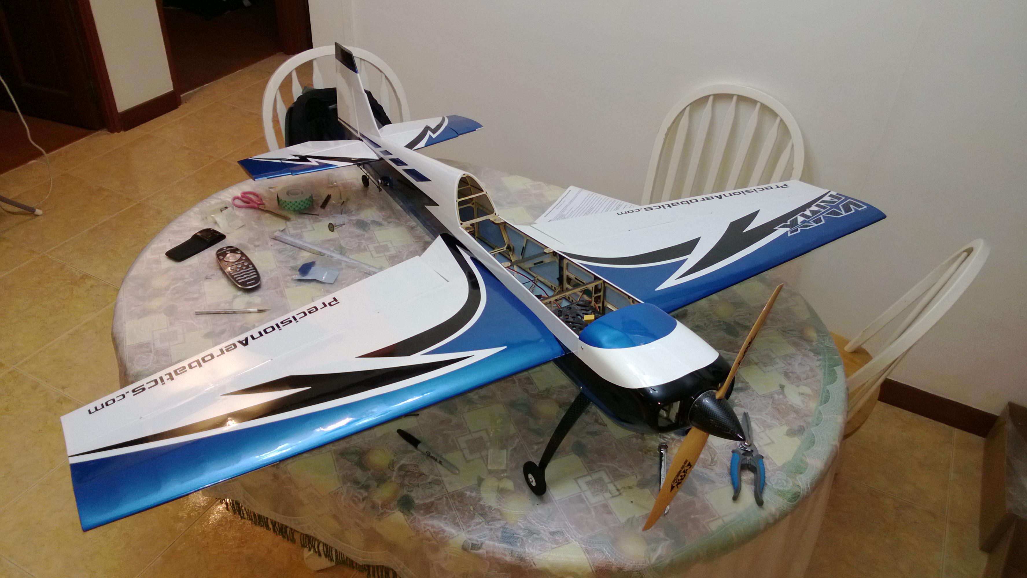
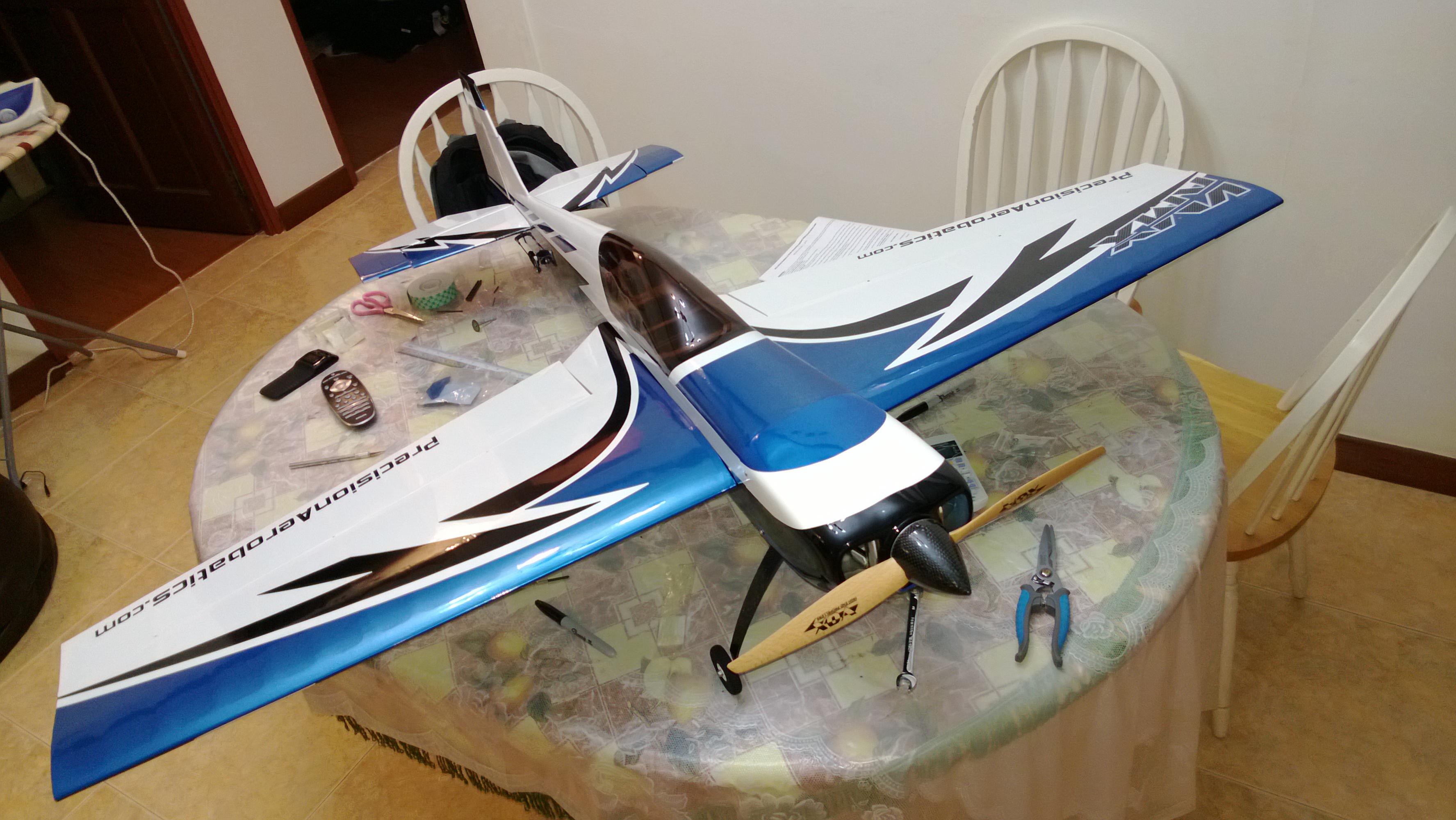
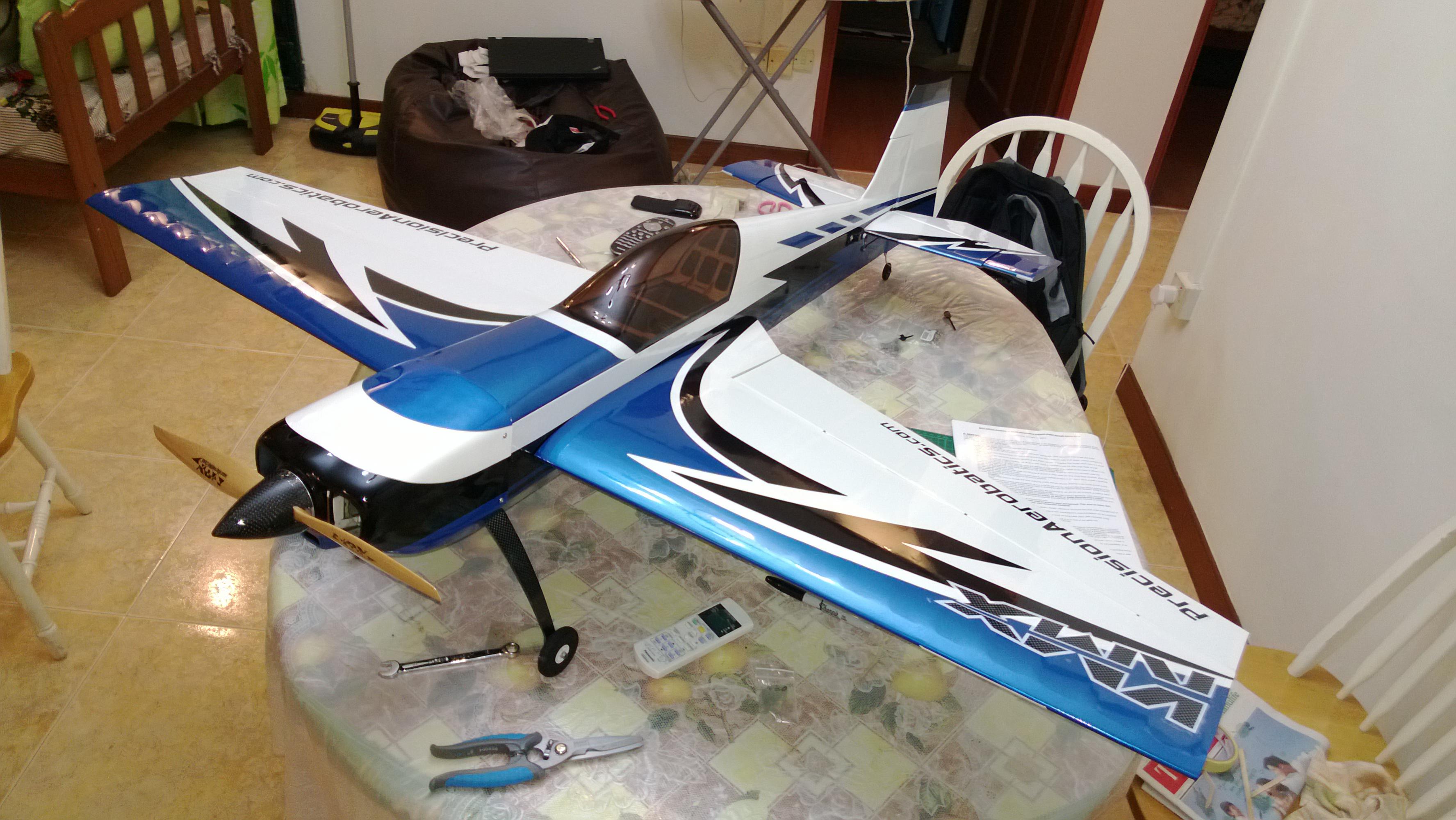
Just did Some Dry Fitting of the parts to see how the plane Looks and ensure the parts Fit Well.
 . For the ost part all Looks Good with No bad Misalignments.
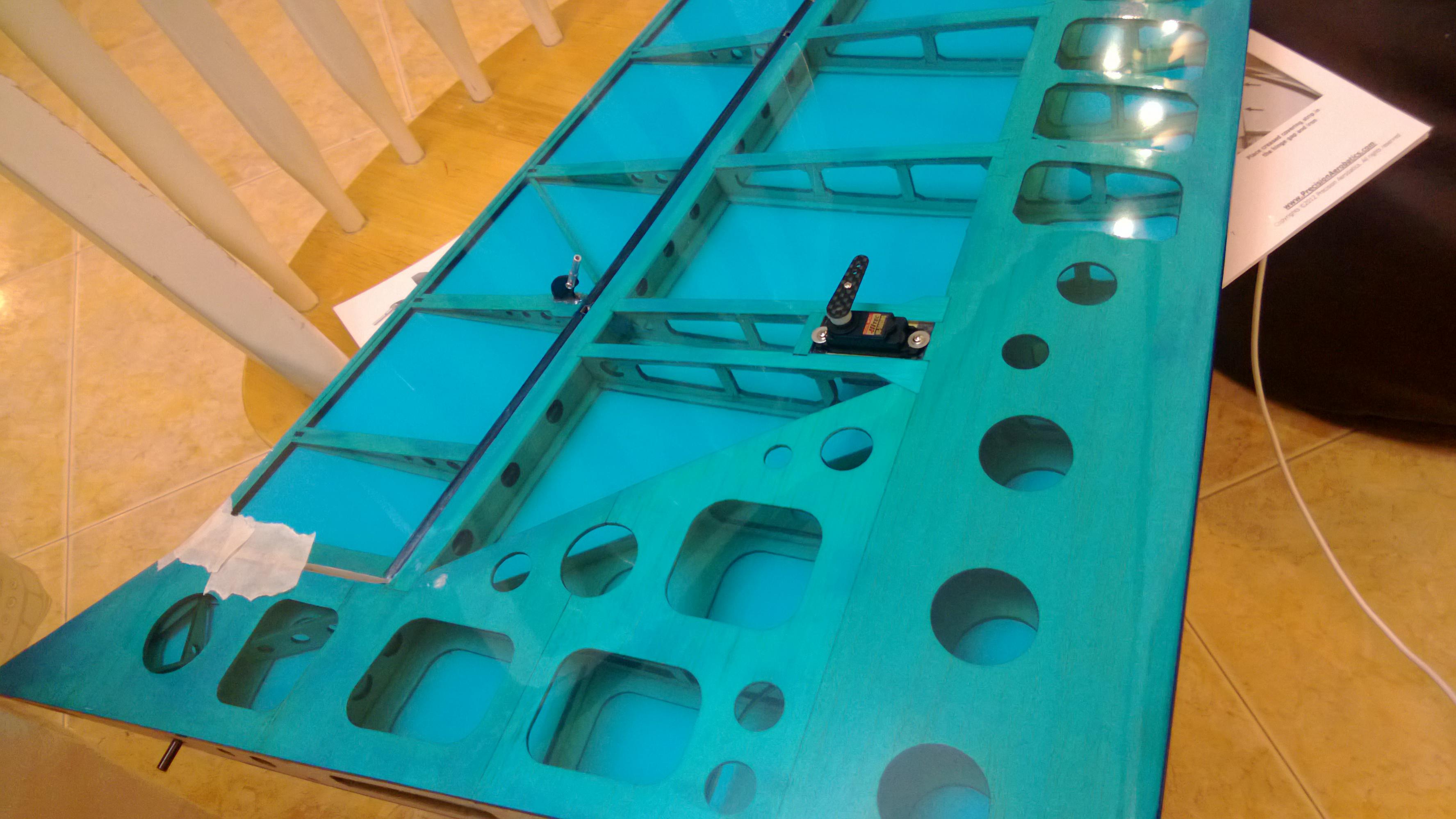
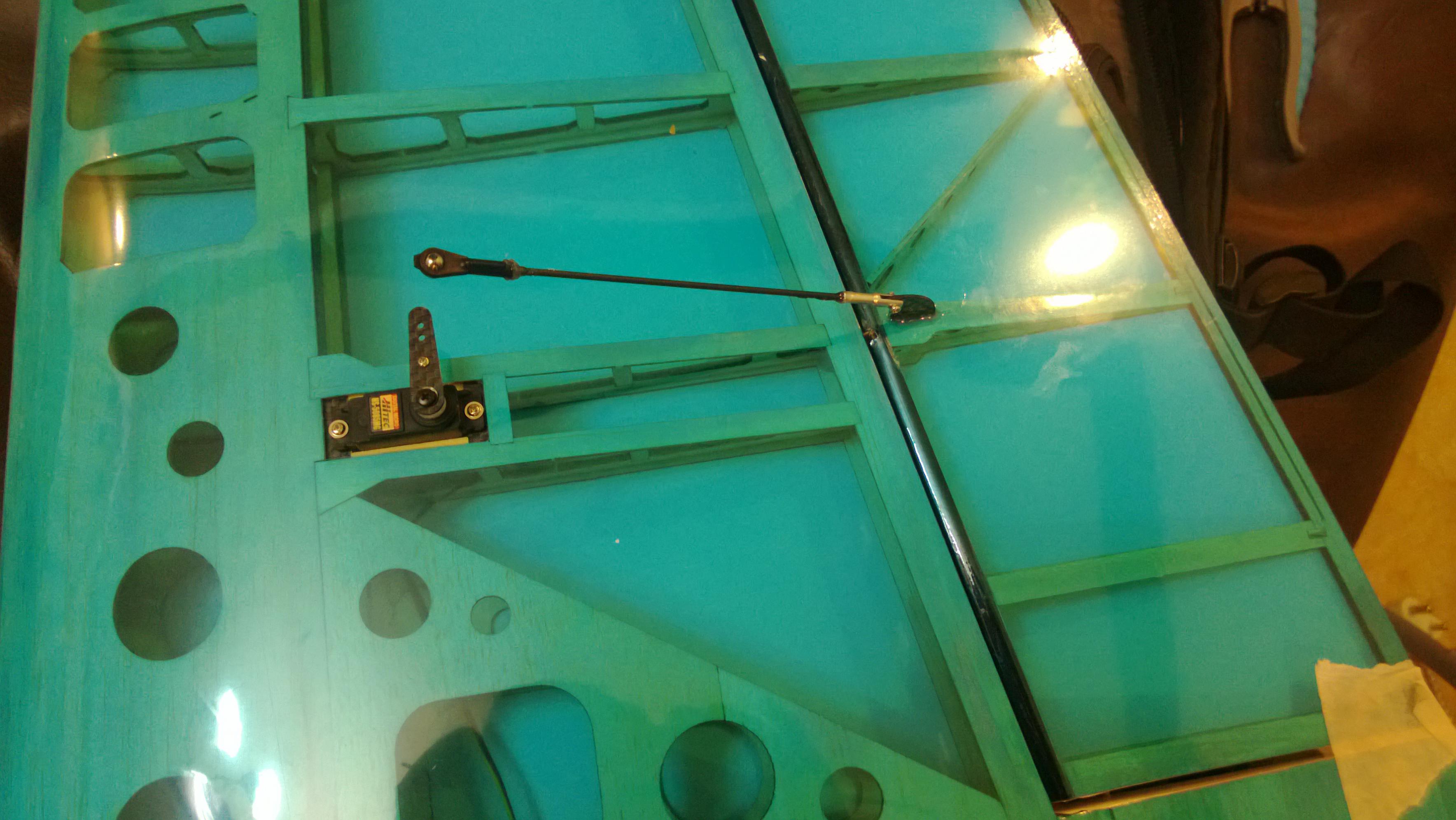
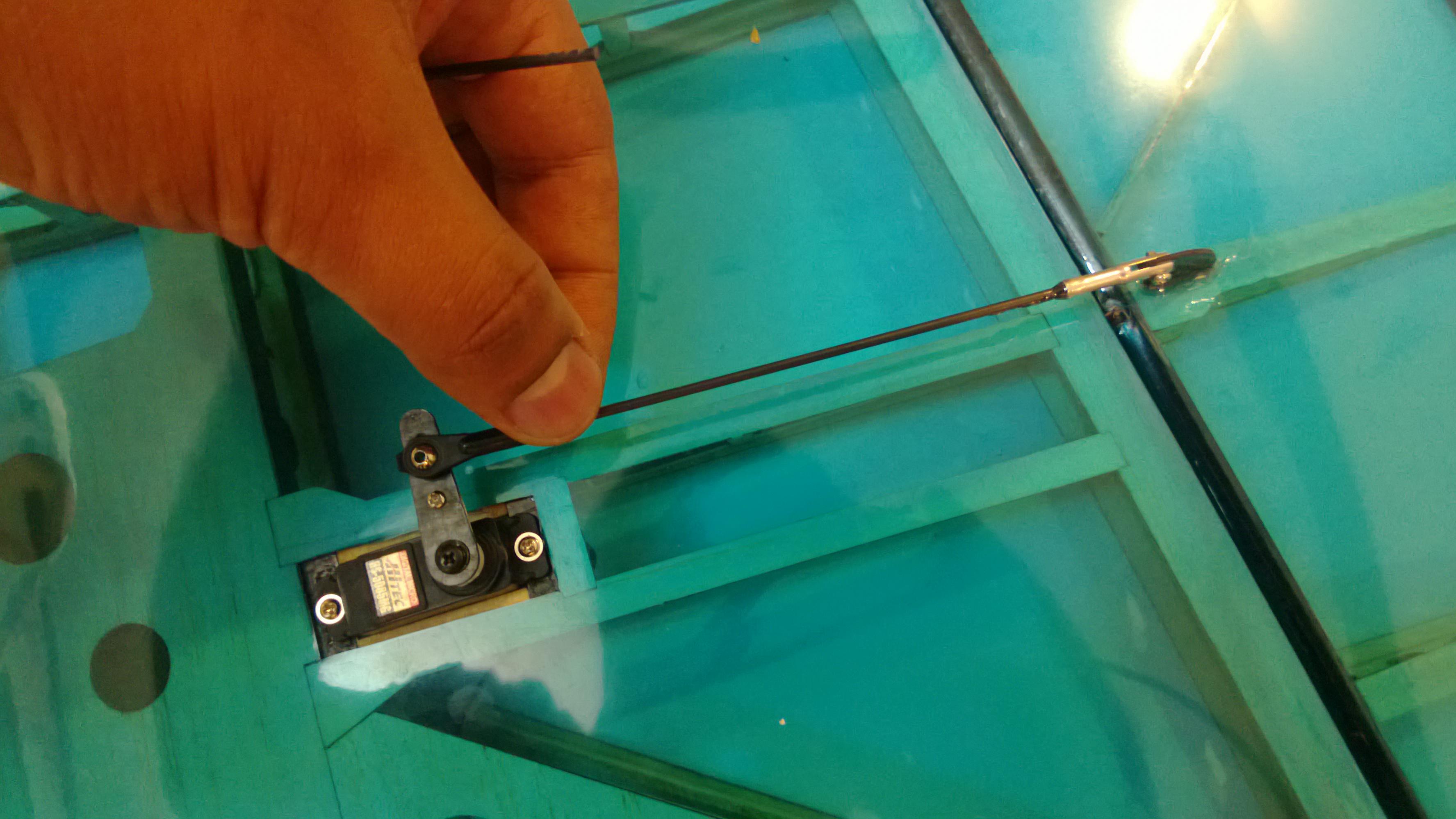
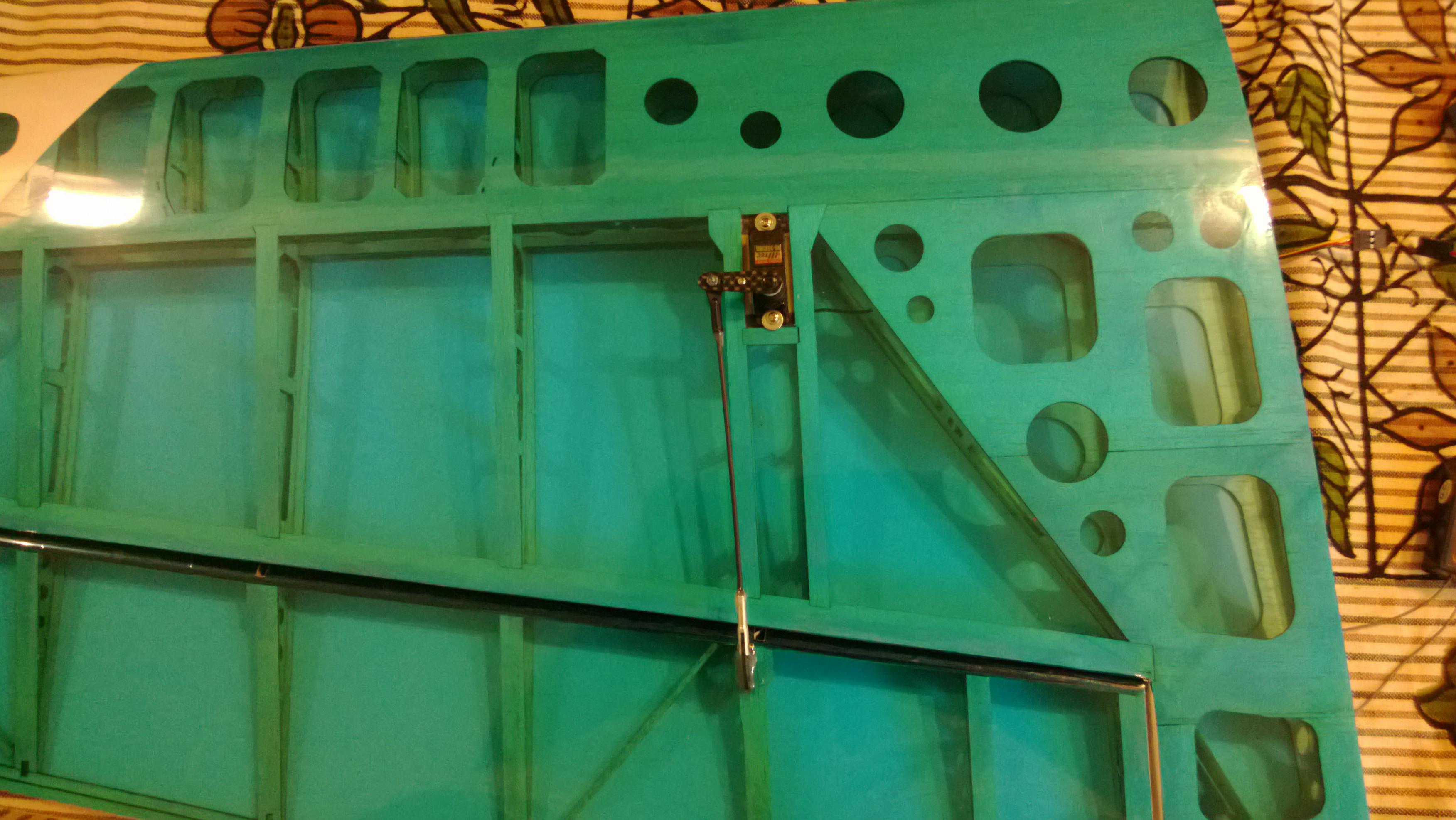
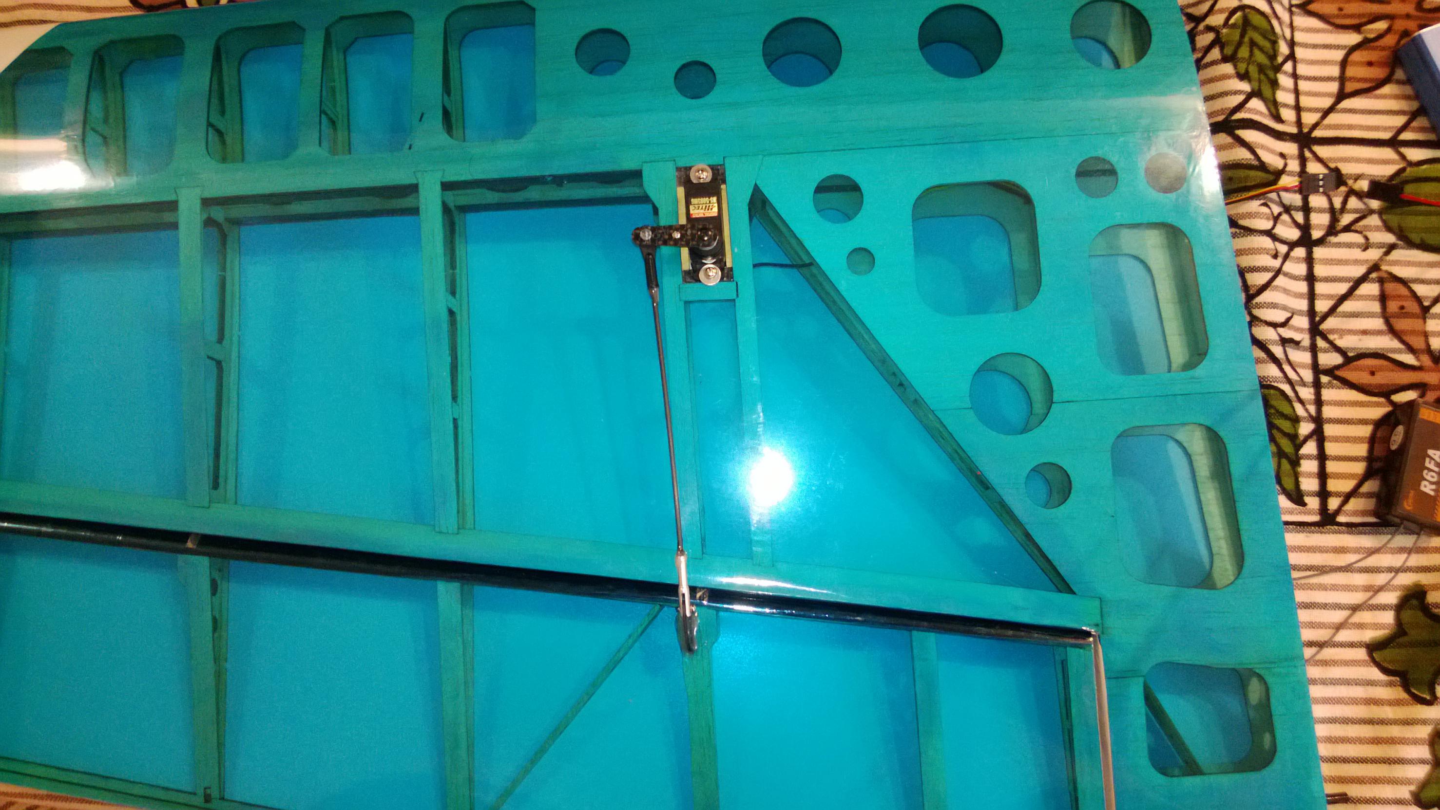
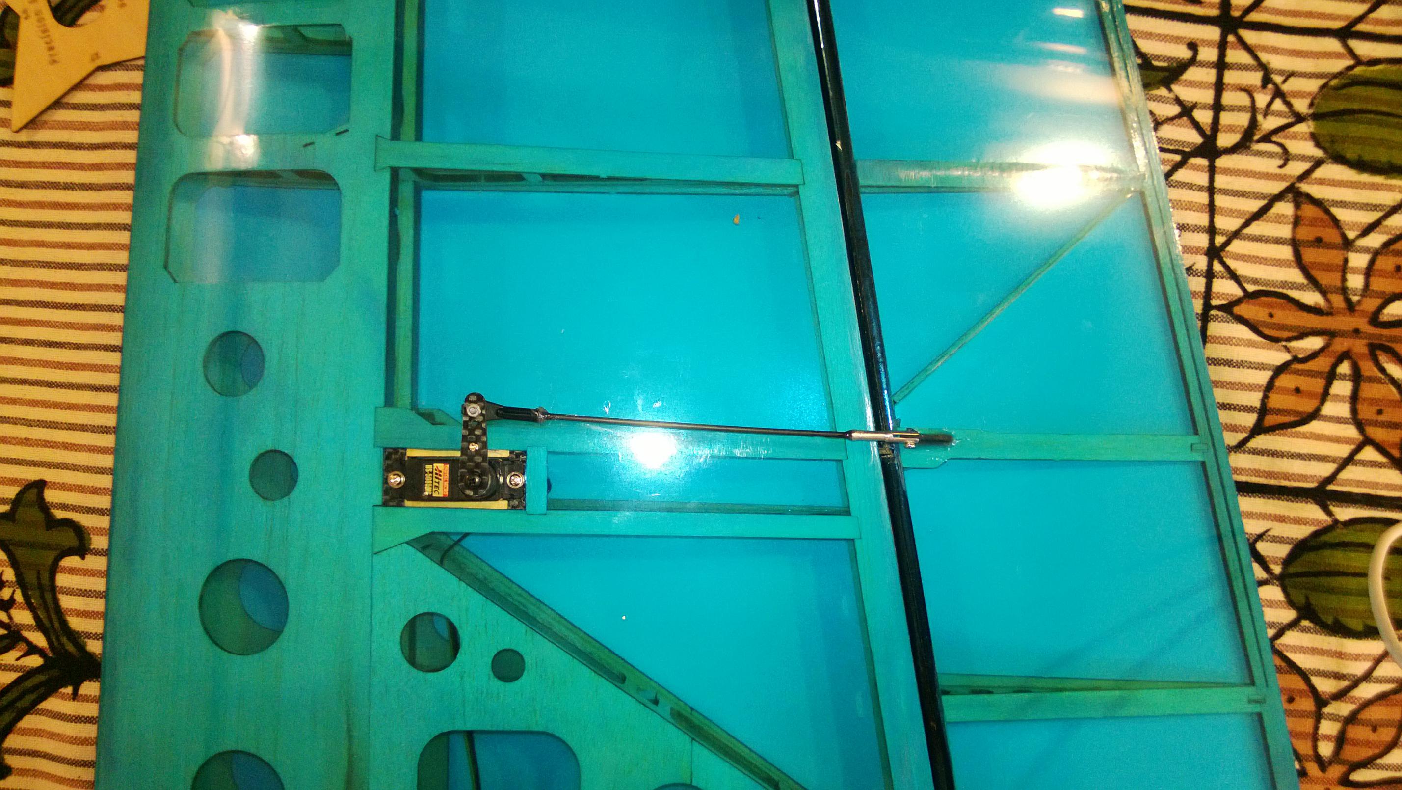
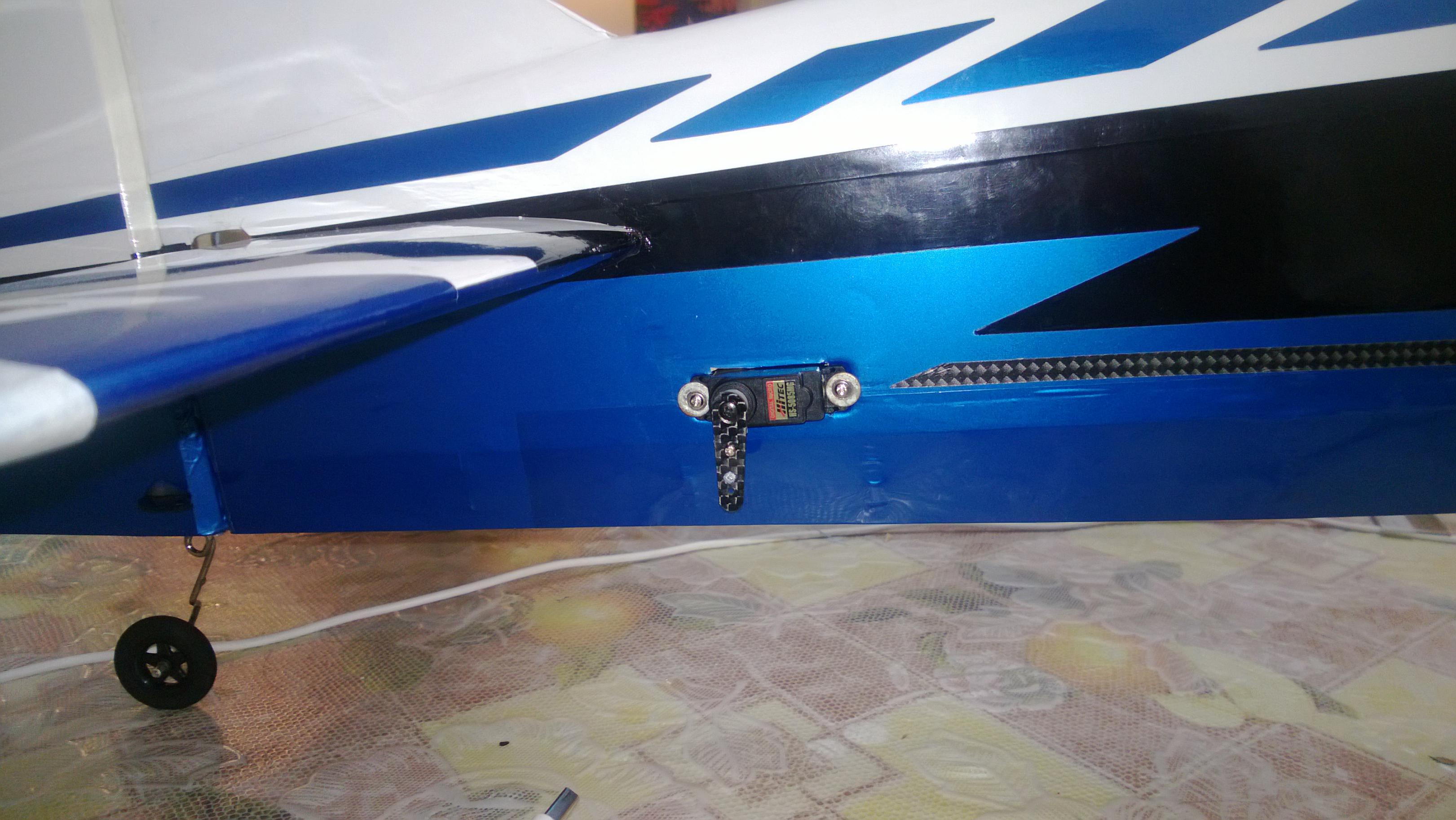
2. Start by Putting in the Aileron Servo and creating the Push rods
Coolest part of the Wings are the pre-hinged ailerons, no messing around with attaching the ailerons they come pre attached.
You may need to sand down the Servo bays a little bit if you are using the recommended 5085MG servos from hitec. Do not use Brute Force as this may dislodge the Servo bays. Just use your Dremel or any other similar machine to sand it down slowly.
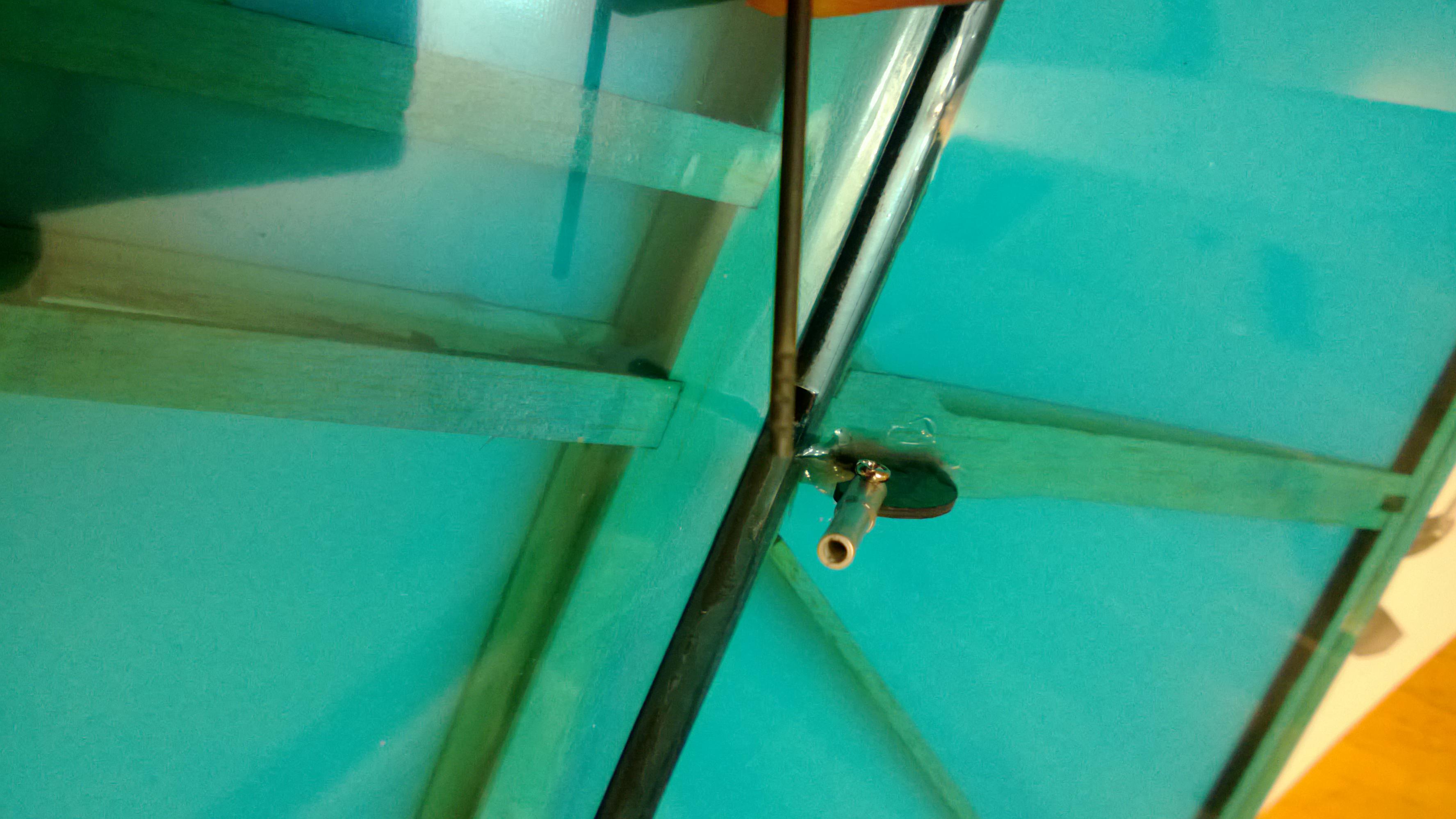
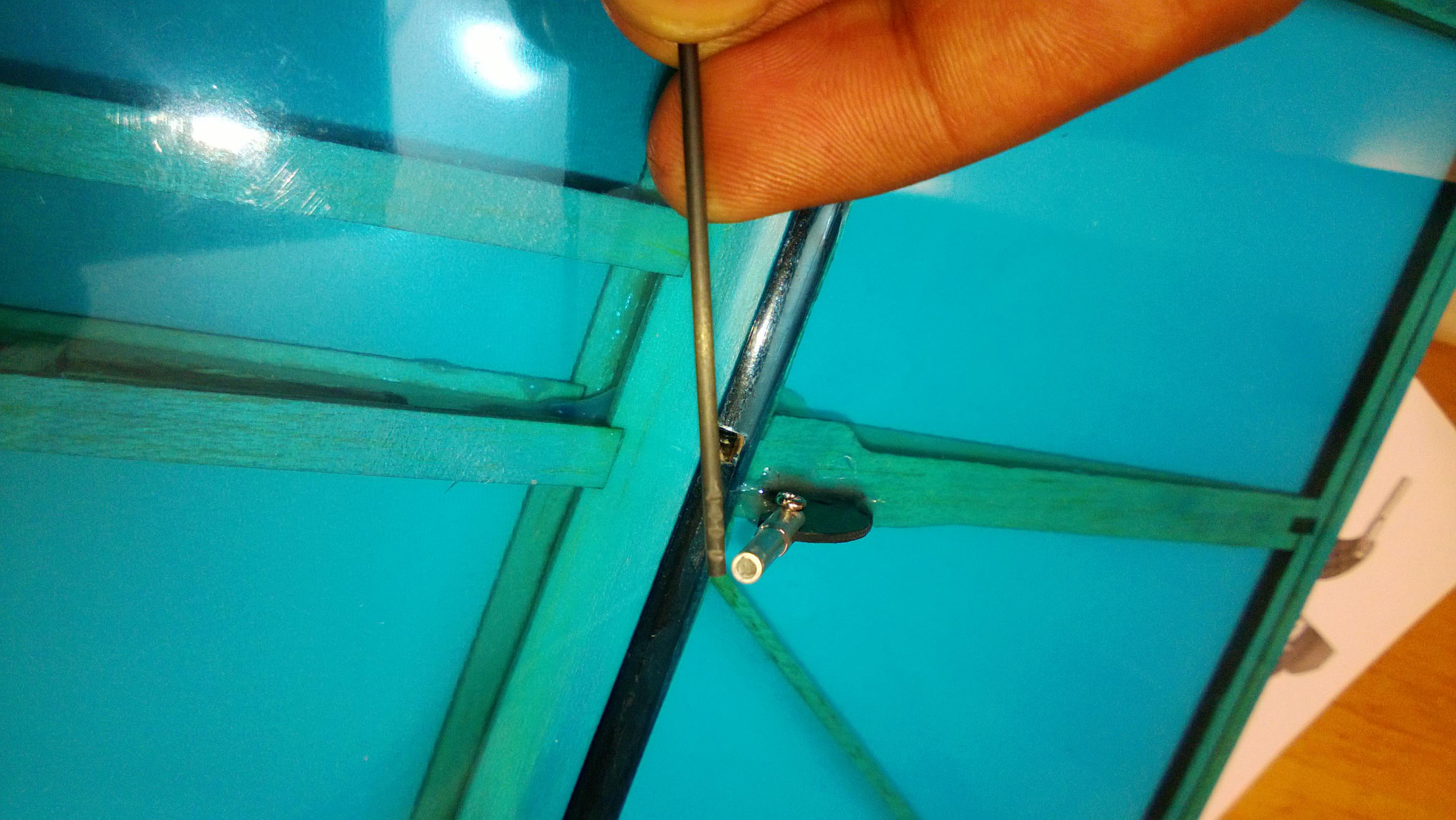
For the Push rods i did the V shaped Etches so that it will hold the epoxy well. Be careful with the cuts as you may end up Cutting too much and hence destroying the CF pushrod.
One thing you Should do Is ensure that you have masking tape on the Ailerons and Securely aligned to the Wings, then measure the Pushrod length properly.
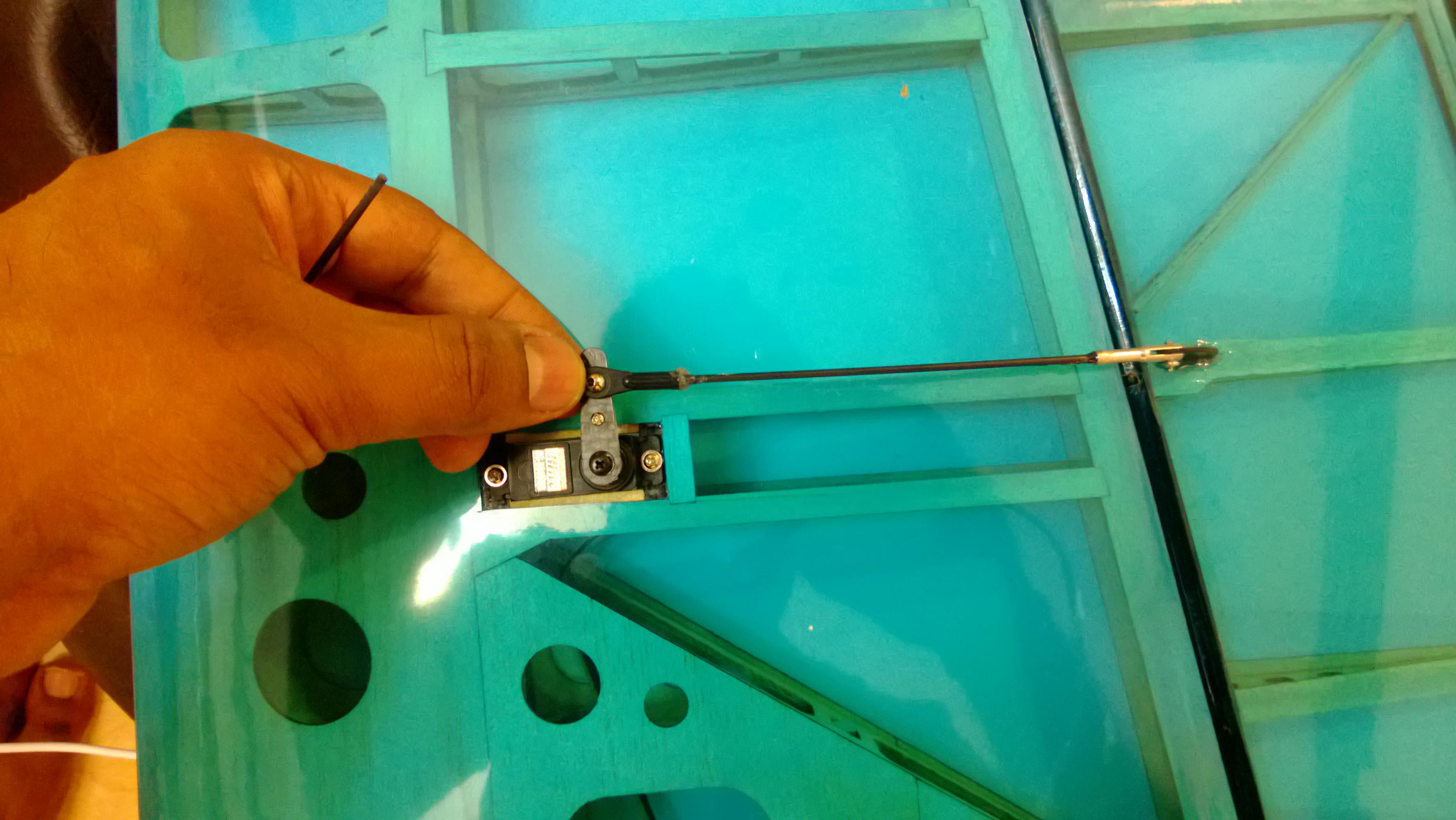
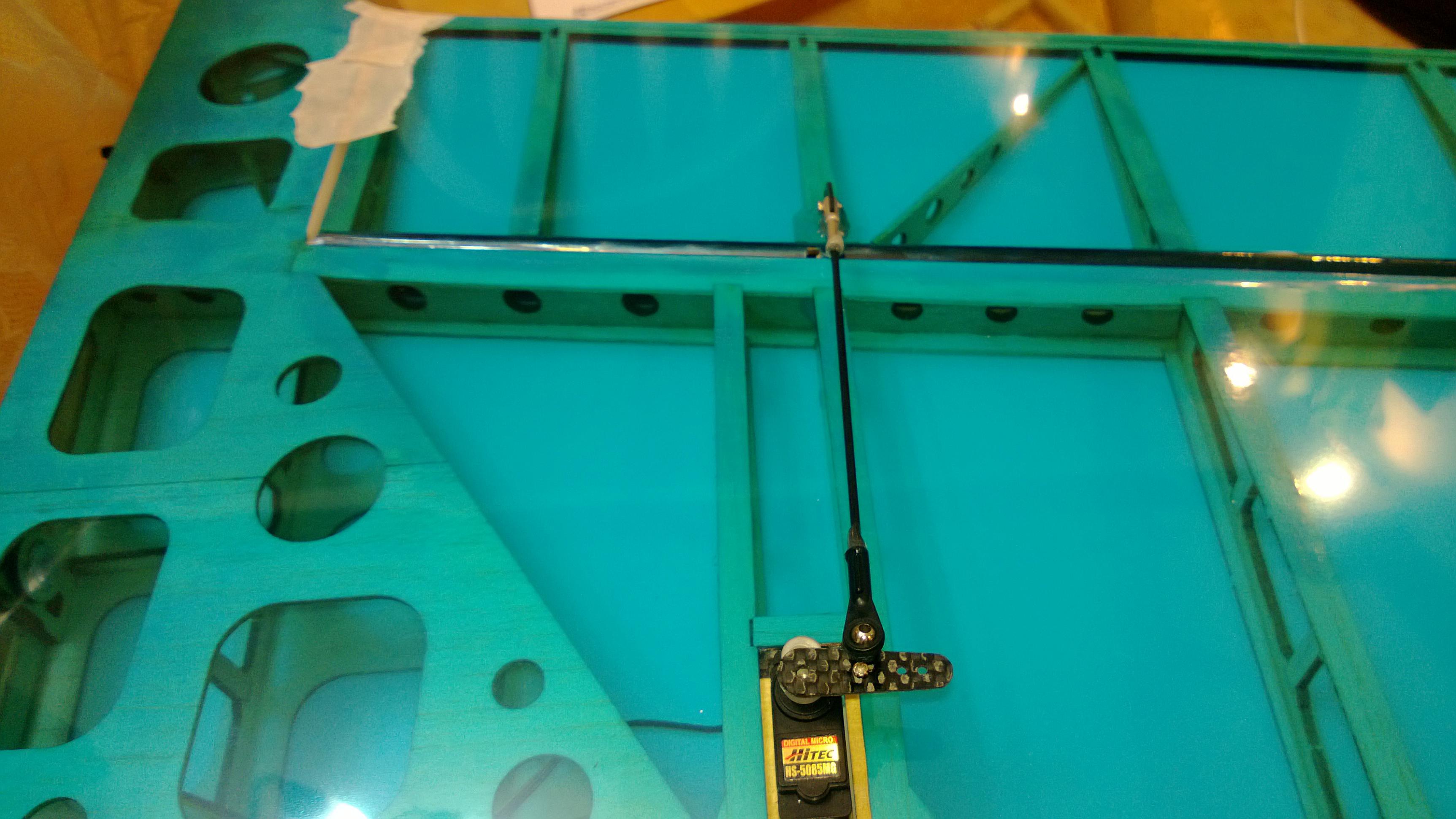
Once the Servo's are in I would like to check for centering, it is good if could visually setup the Servo arms to 90 Degrees (use Subtrim) in the build thereby giving you the little room for error and using Subtrimming later on.
This will help to get the Correct Physical geometry for the setup and i have seen it needs much less subtrimming later on.
I was able to get Perfect Geometry with the setup mentioned in the manual.


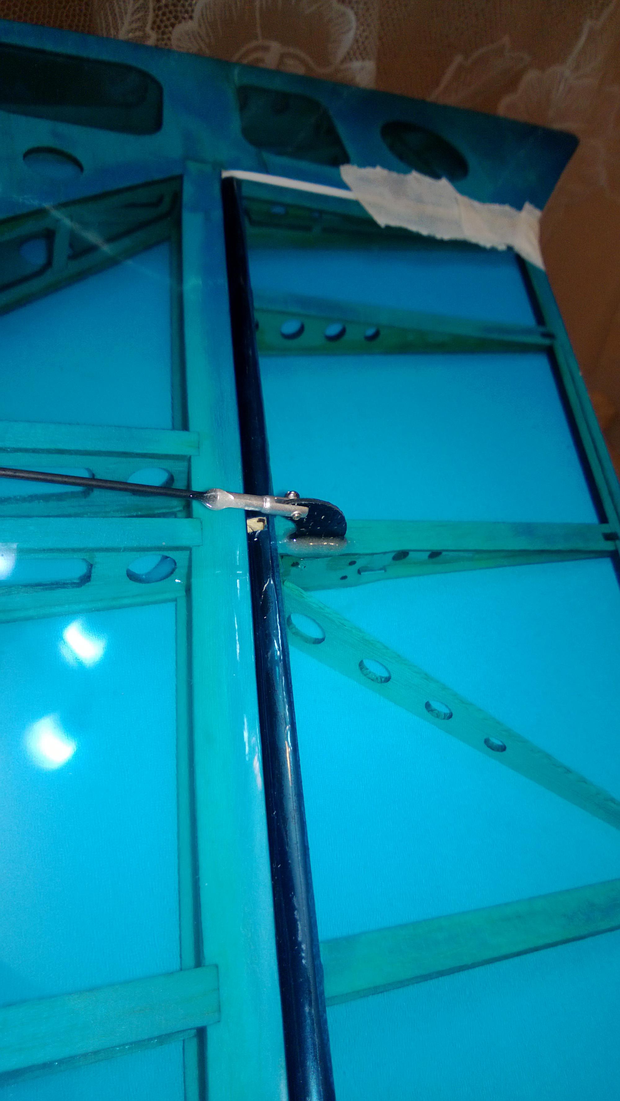
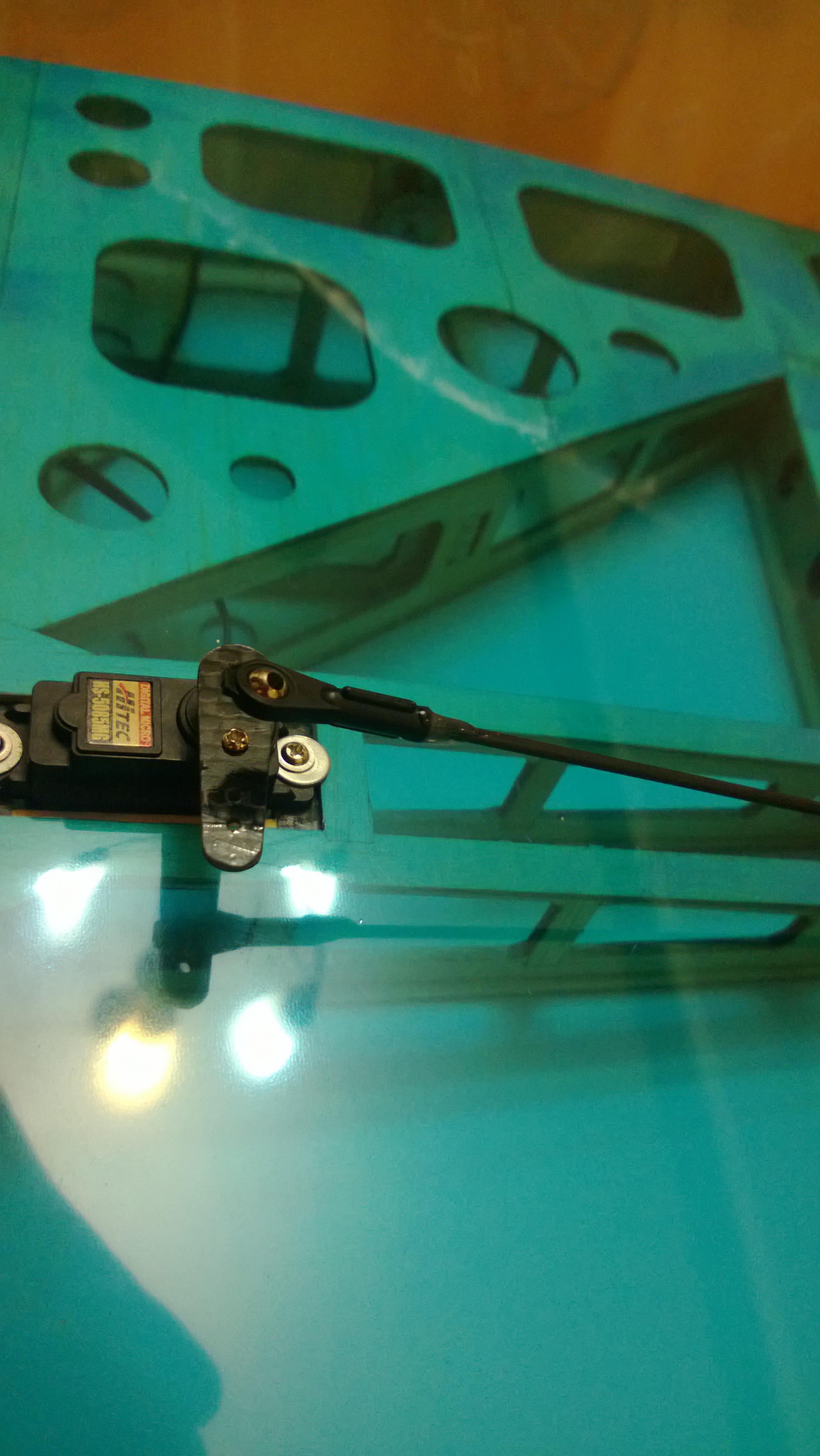
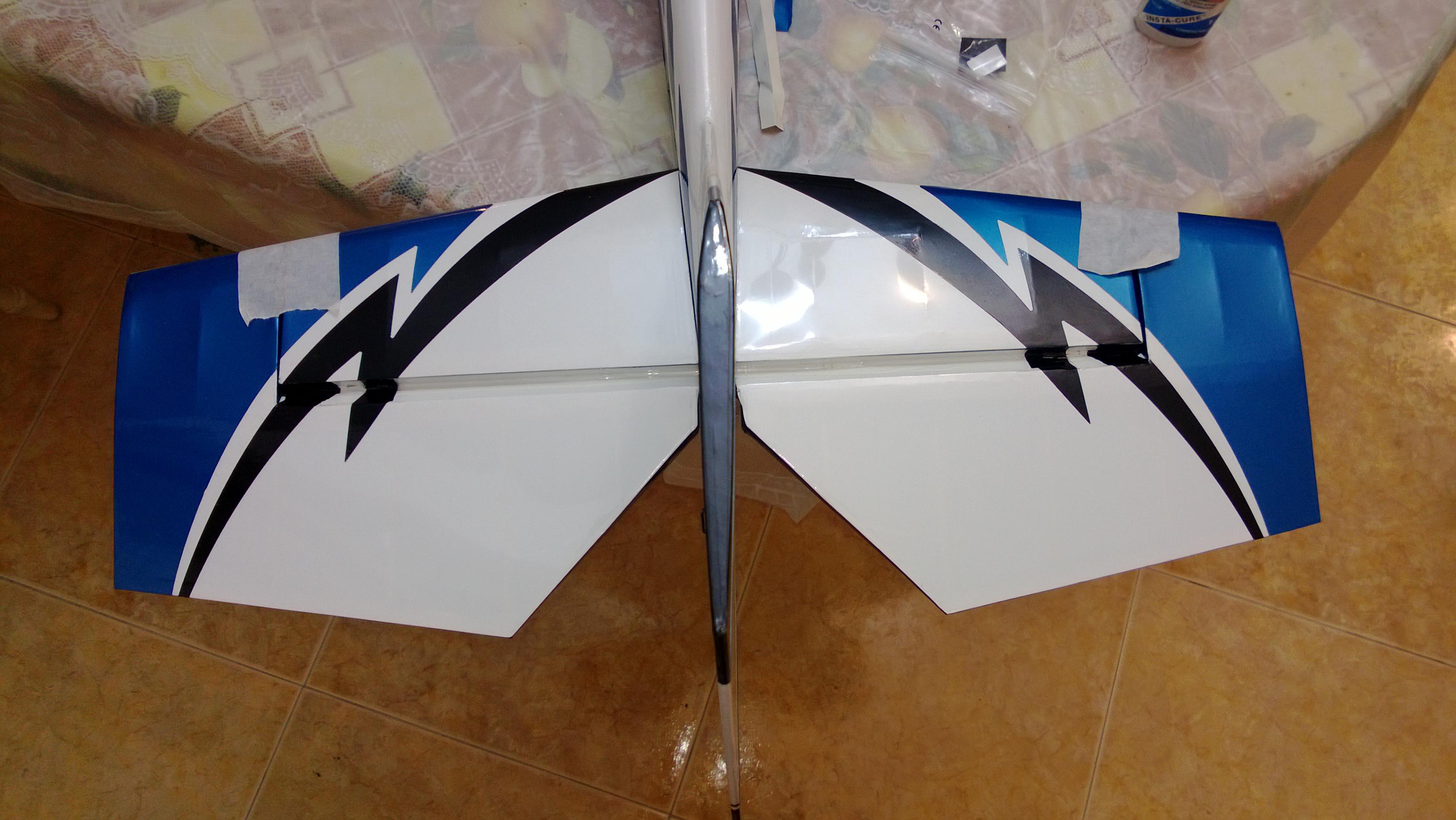
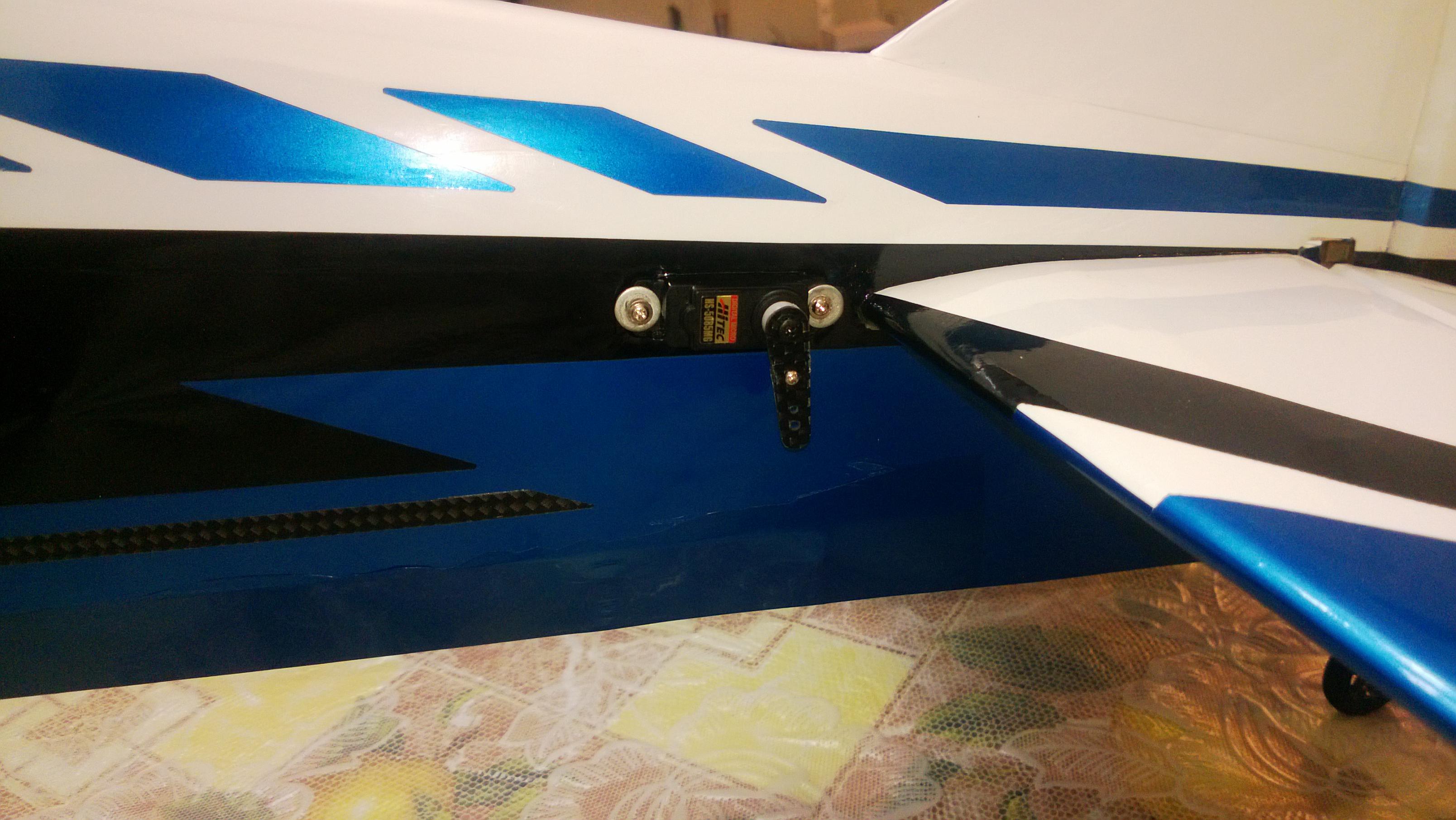
As can be seen here after i got the Servos and the Pushrod all in place for both the ailerons there is very minimal need for subtrim.
I was surprised to see perfect alignment on one of the wings and hence was getting the correct throw for 3D.


If you were unable to get this straight use Subtrim.
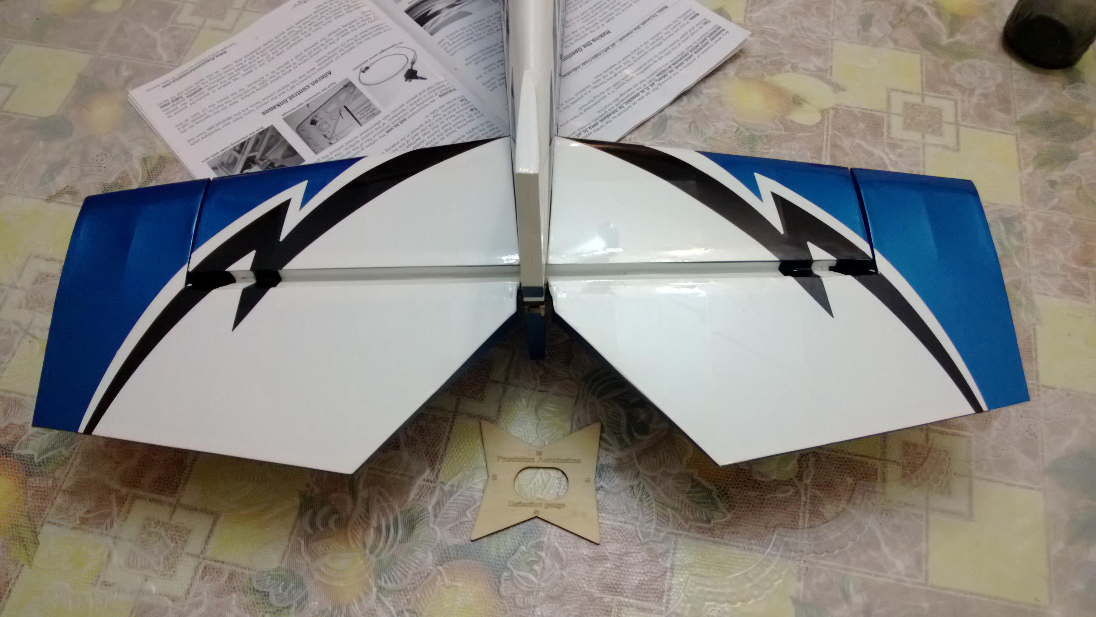
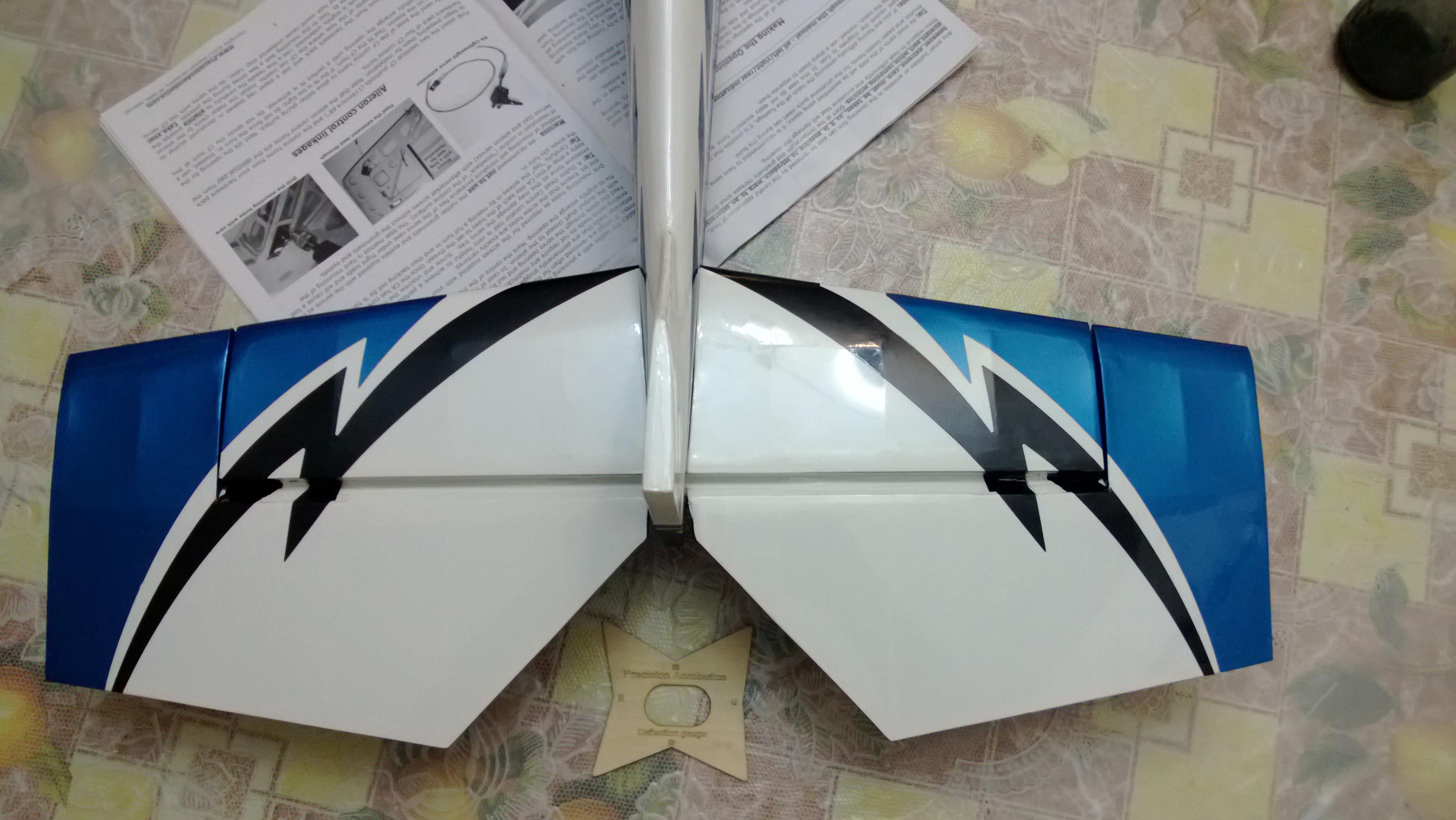
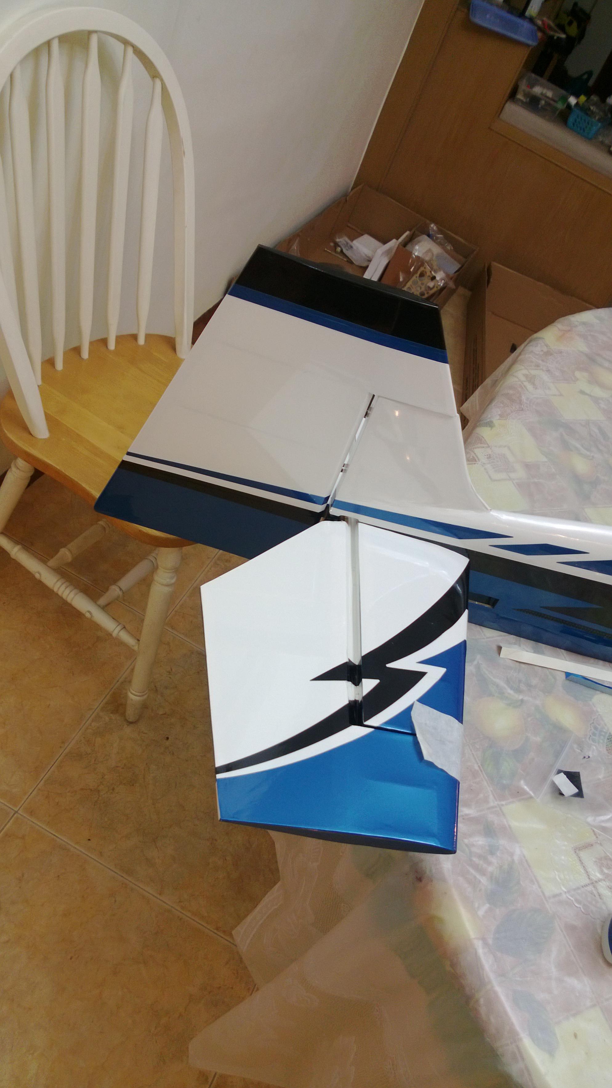
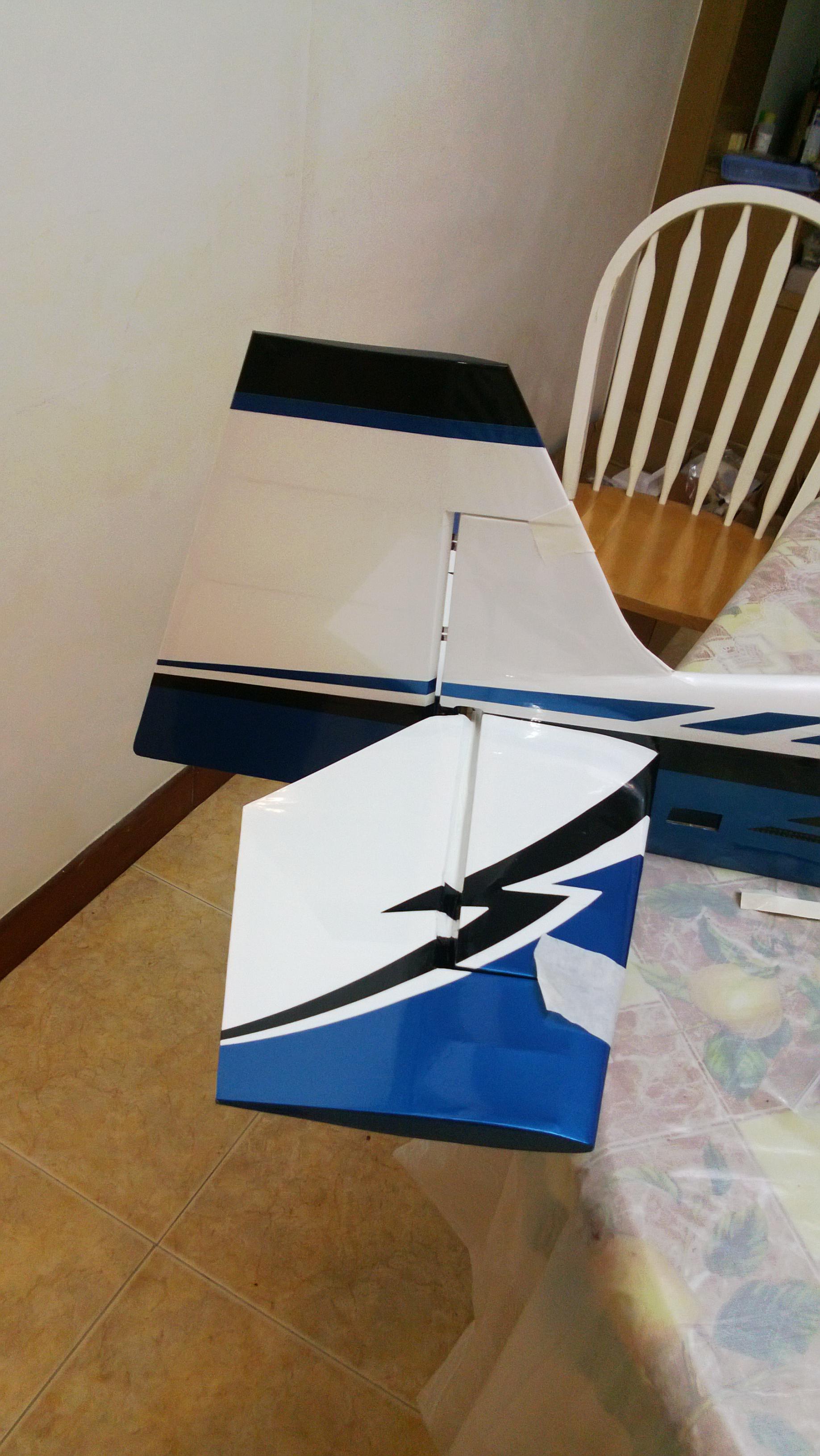
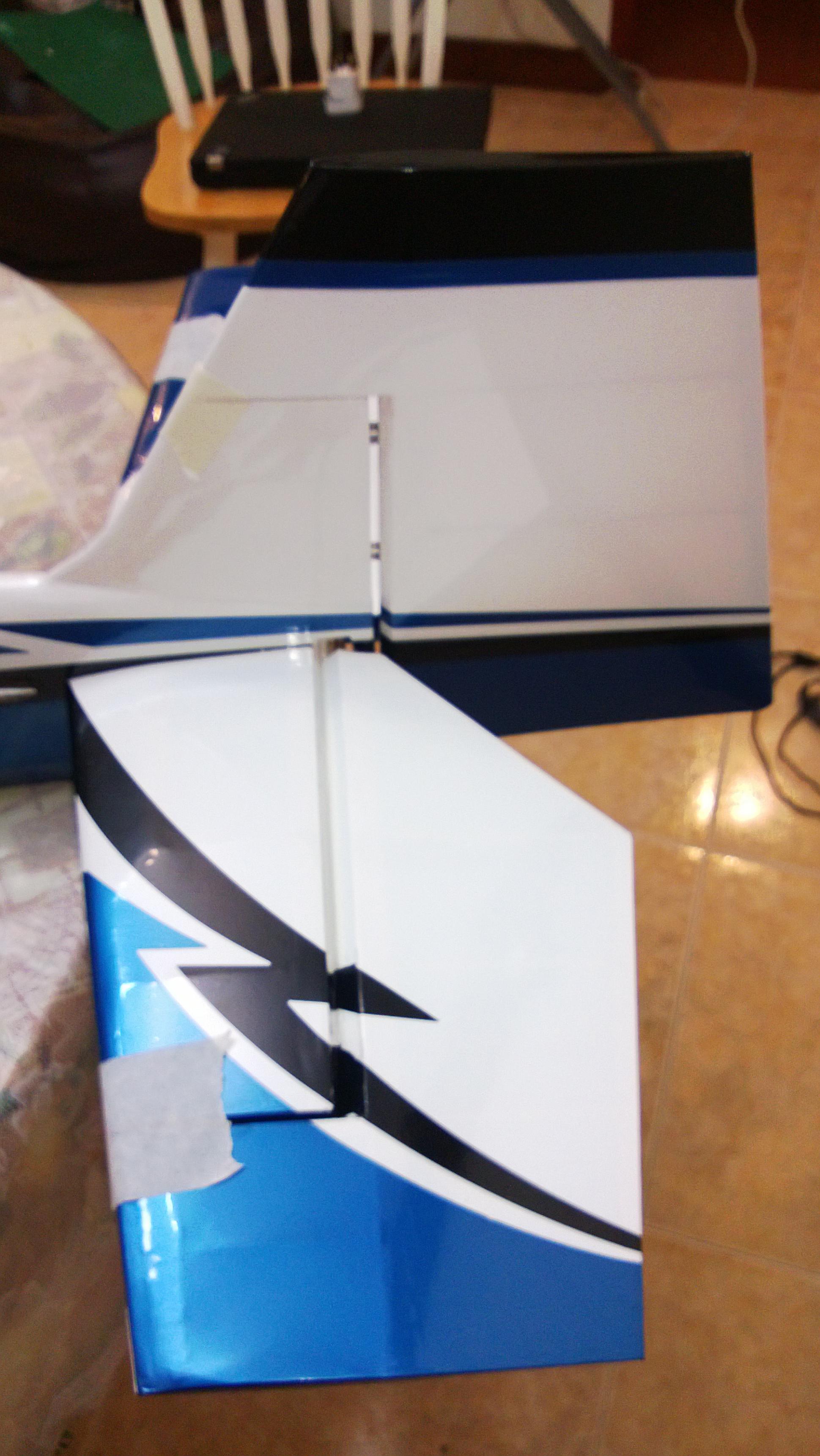
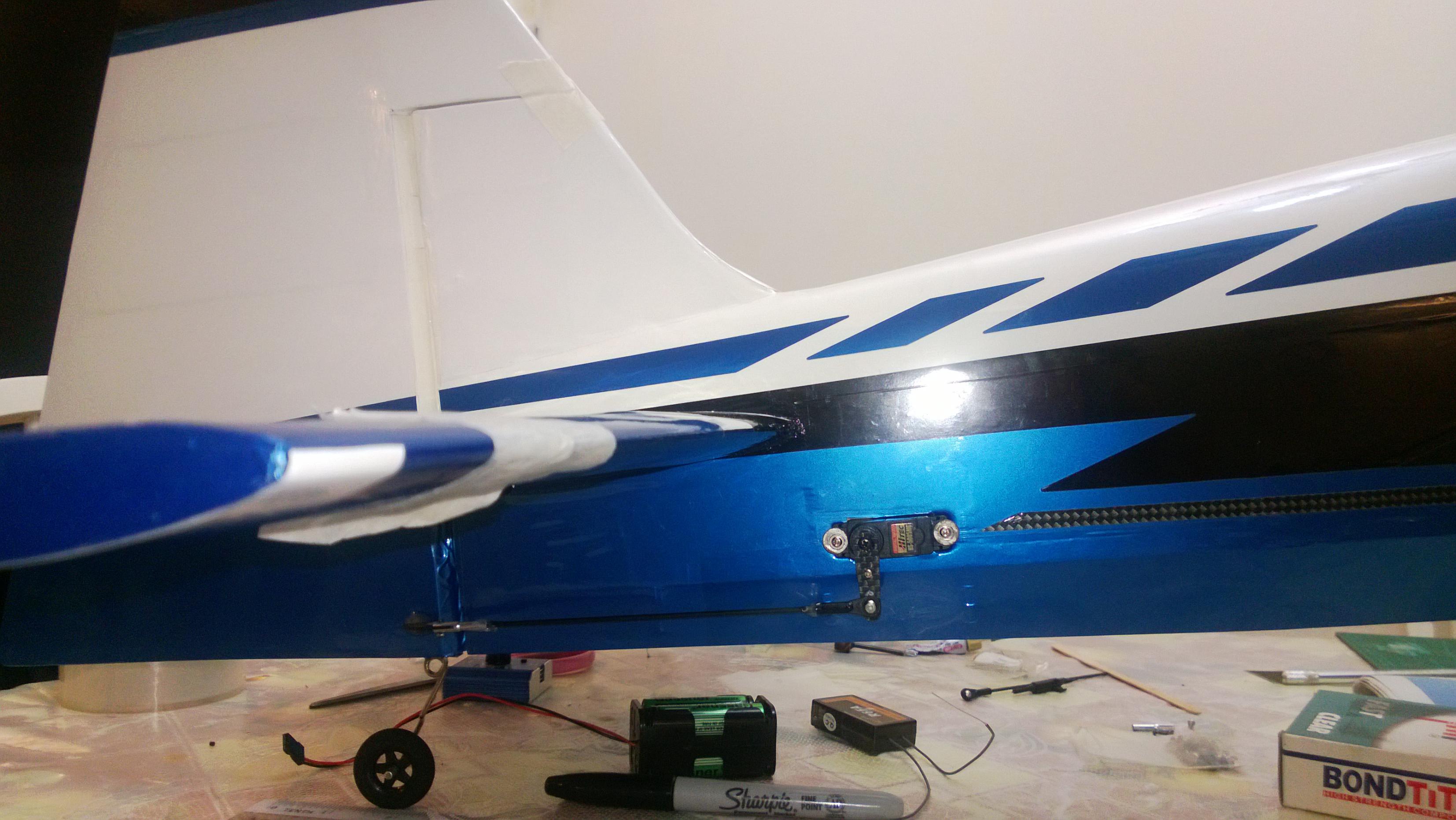
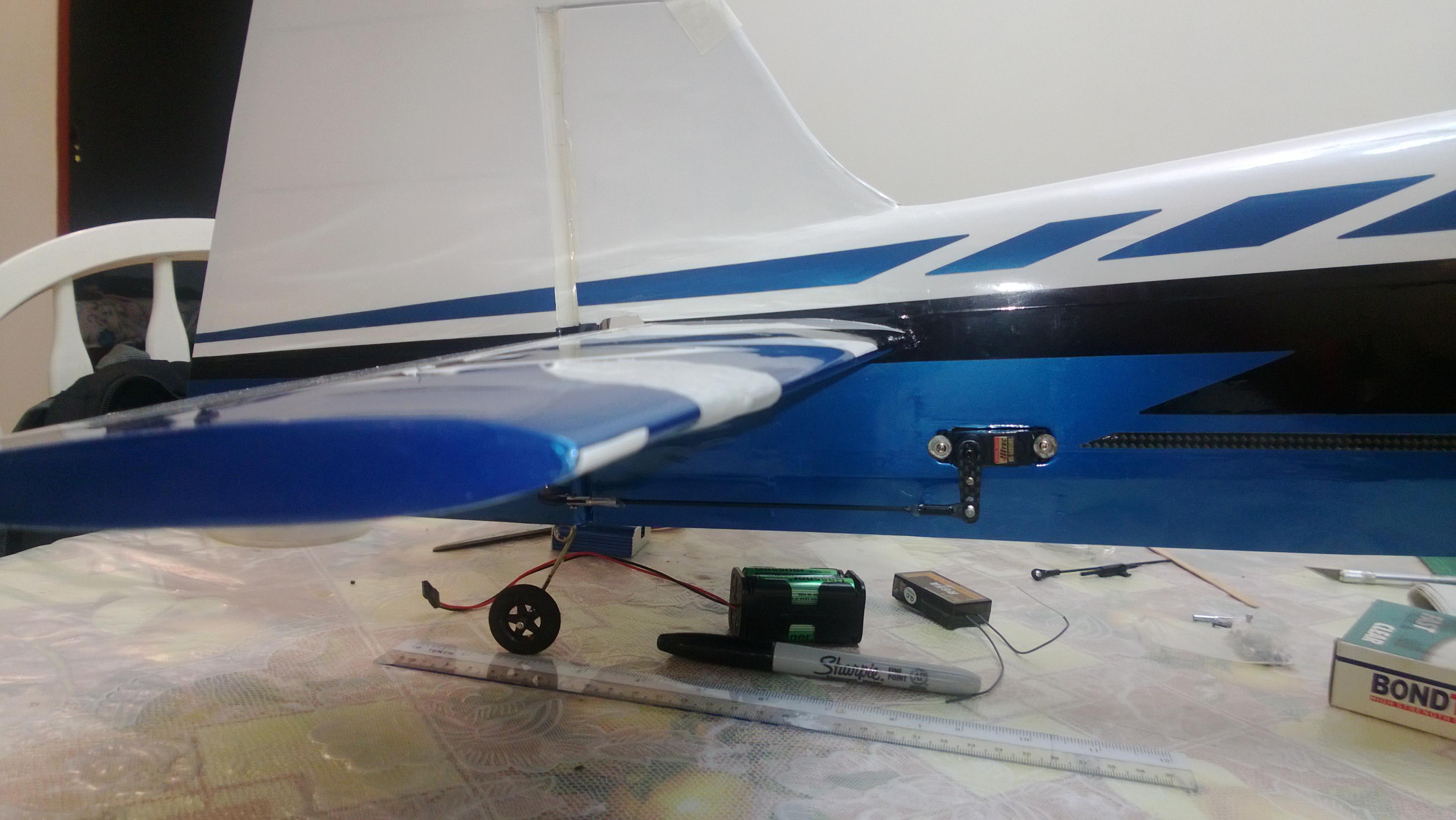
3.Moving on to the Fuselage now, Connecting the Elevator
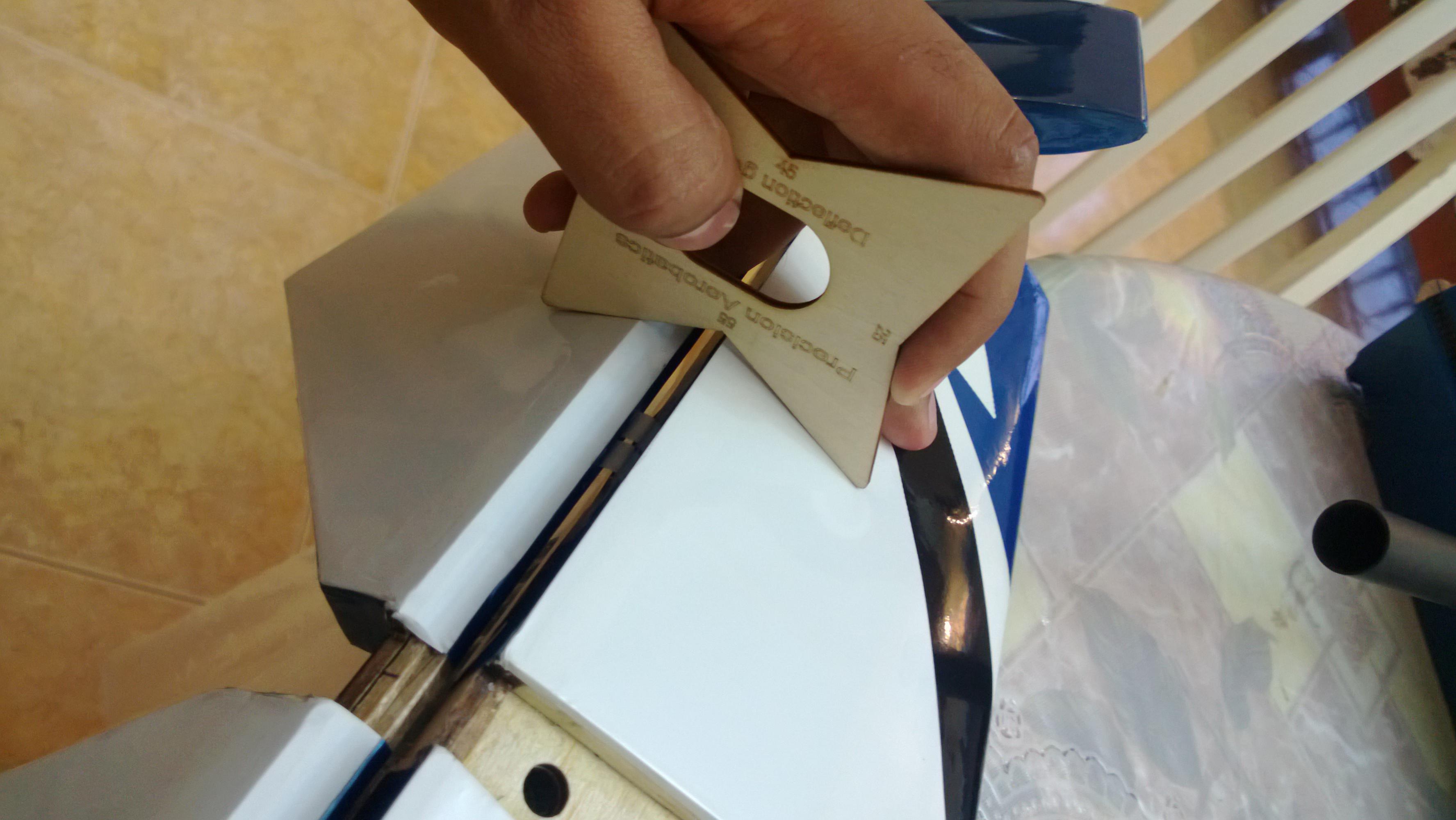
The elevator comes Pre-hinged to the Horizontal Stab on one side, I just measured the right throw i needed (55 Degrees) to be precise. I opted for a couple more degrees to offset for any errors. (Especially while Sealing the Hinge gap.)

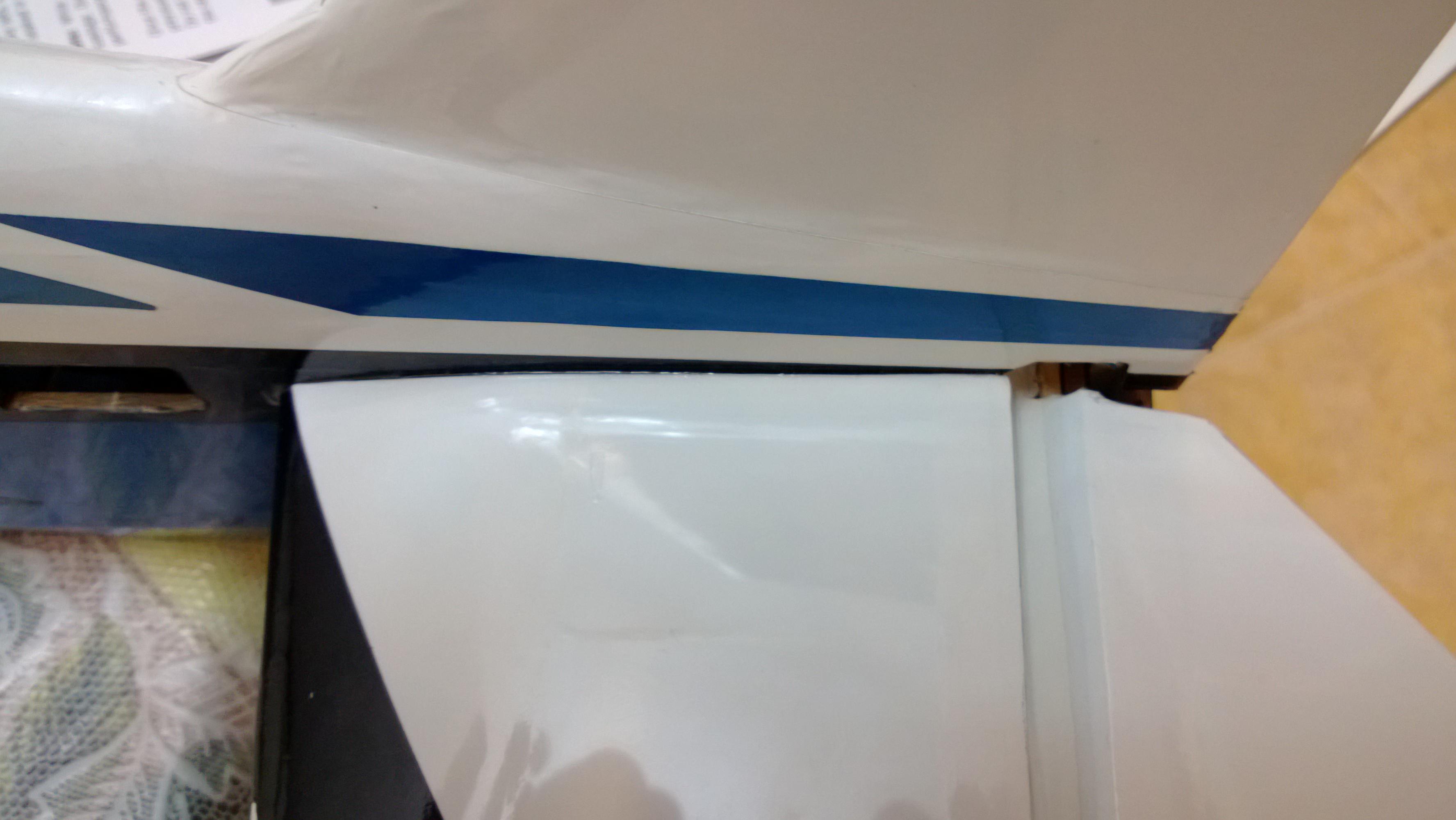
Ensure that you have Cut the balsa wedge and that the Horizontal Stab Goes well in to the Fuselage, Use sandpaper to sand down if the Fit is too tight, DO NOT USE FORCE .
.
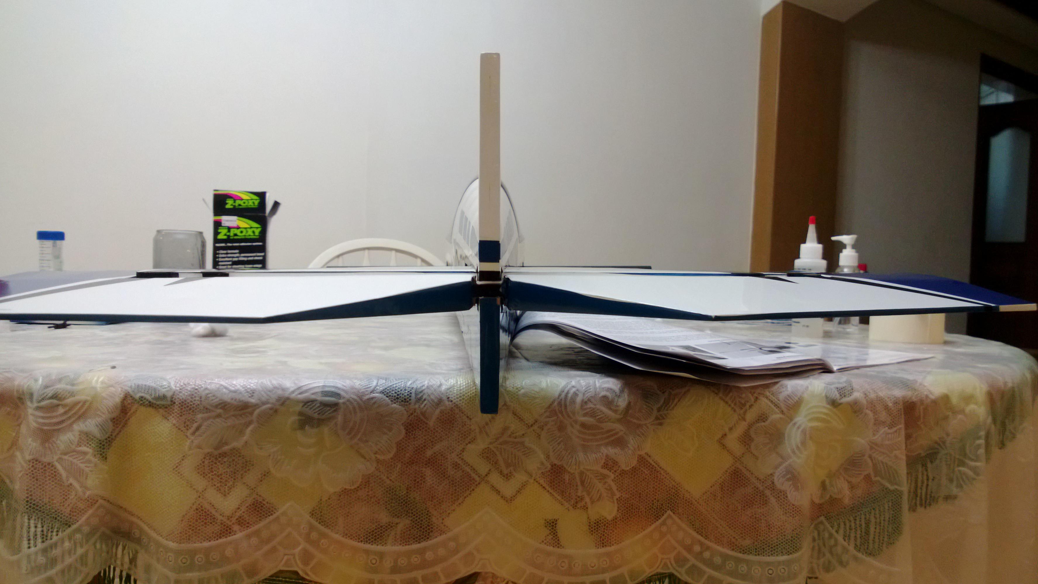
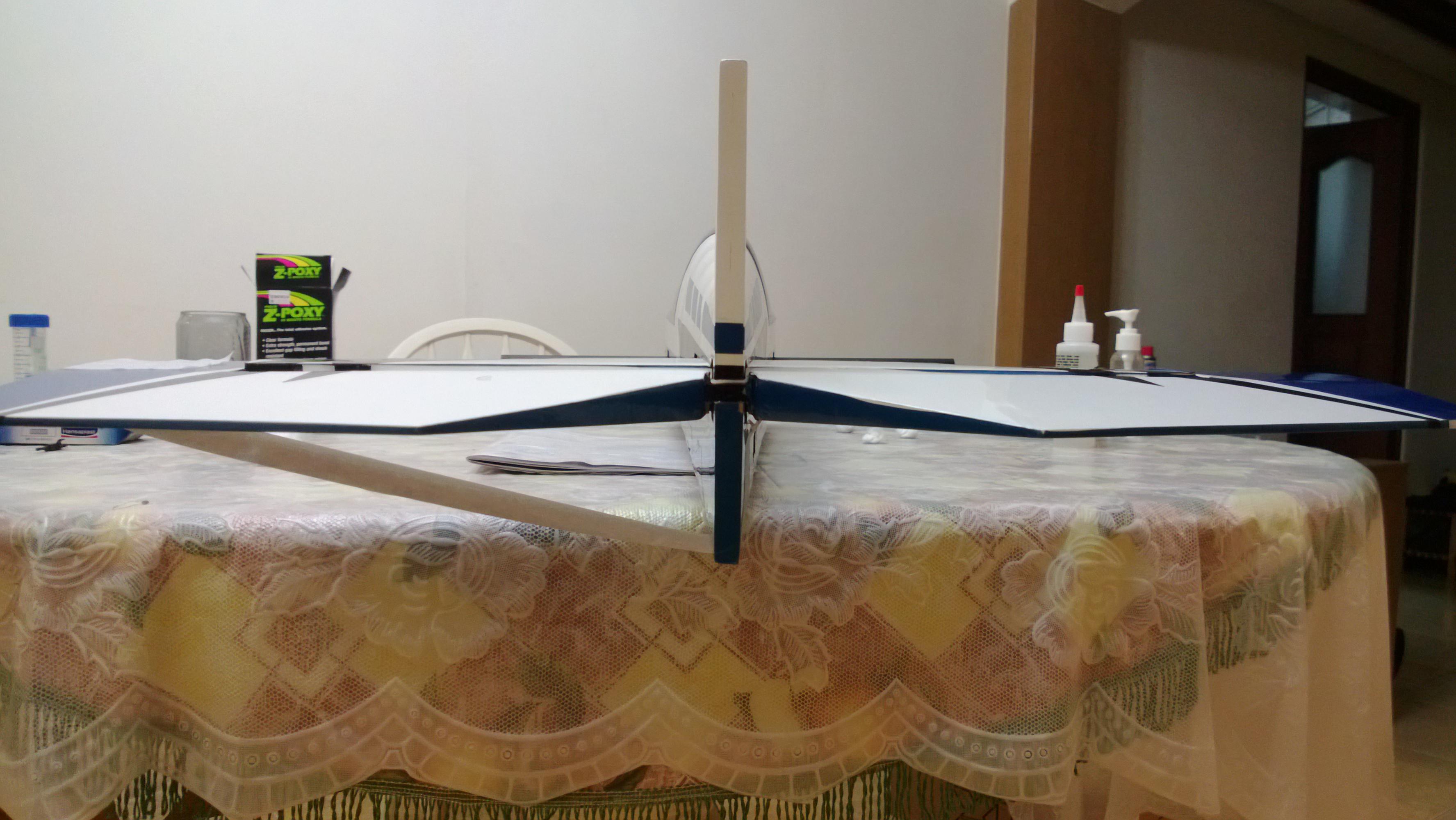
In my case i saw a few mm Warp/Misalignment of the Elevator section to the Wing Tube.


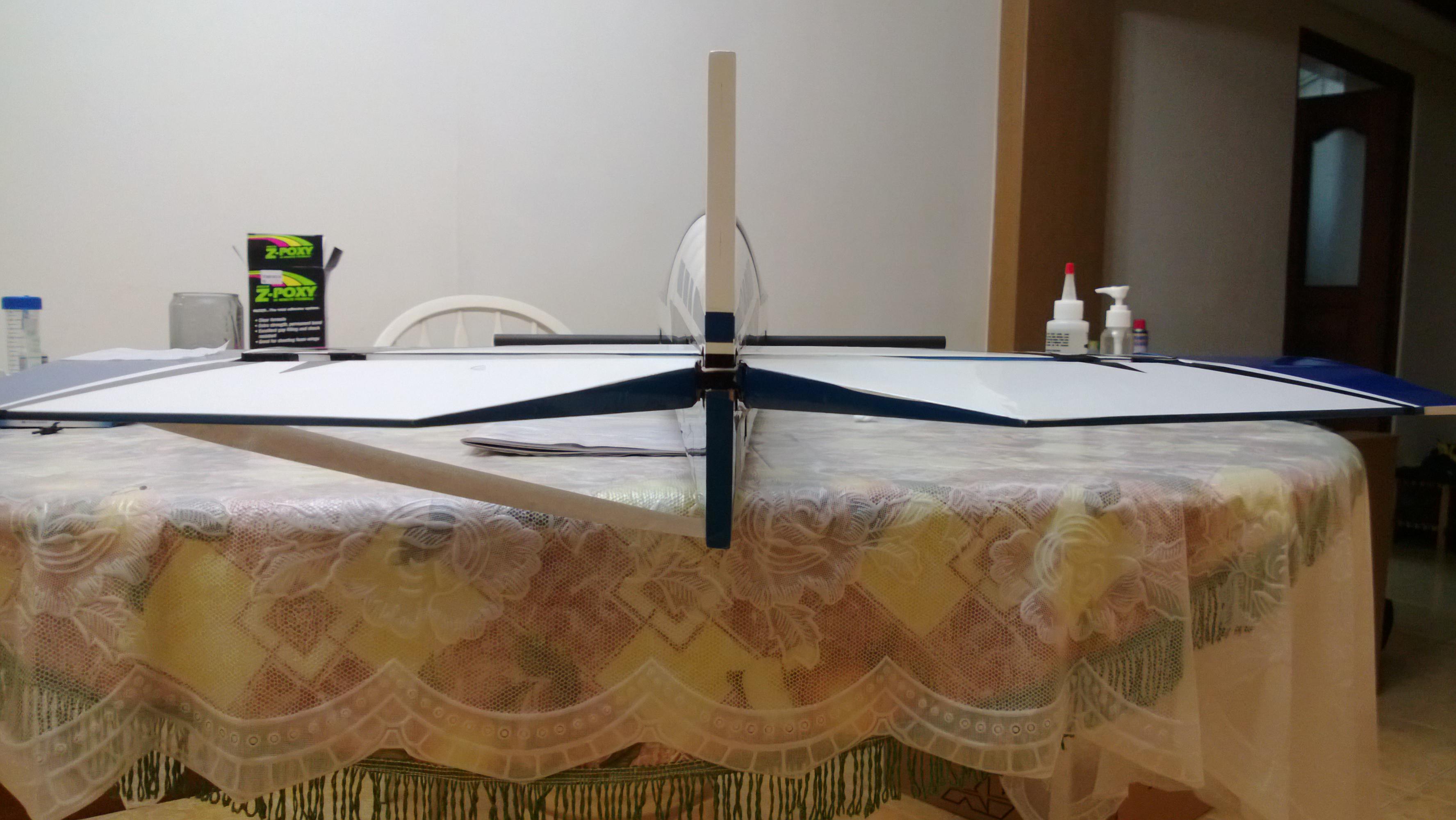
Just sanded down a little bit from one side and it was Fixed, got the perfect alignment. Ensure that you have this setup correctly.
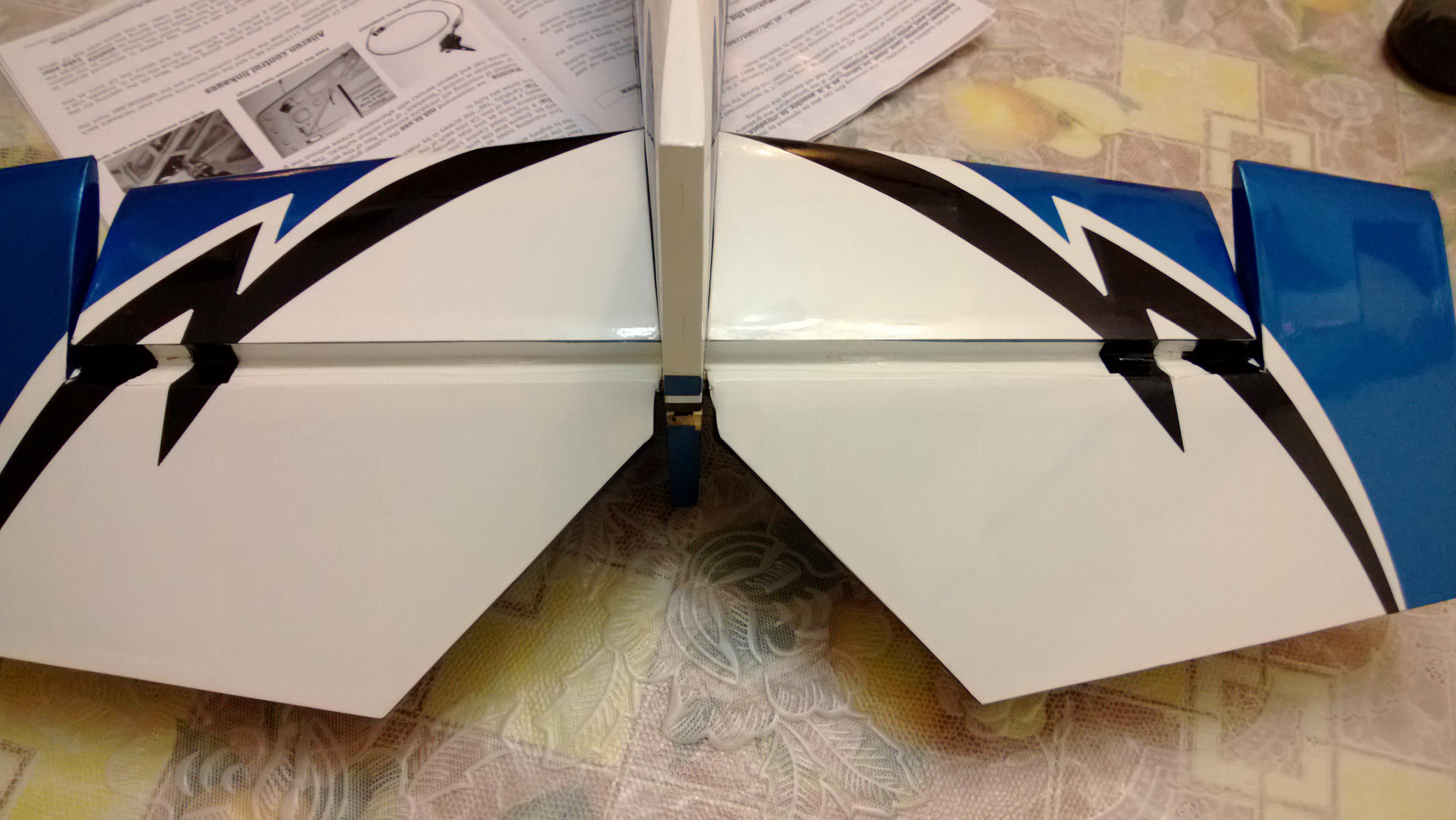
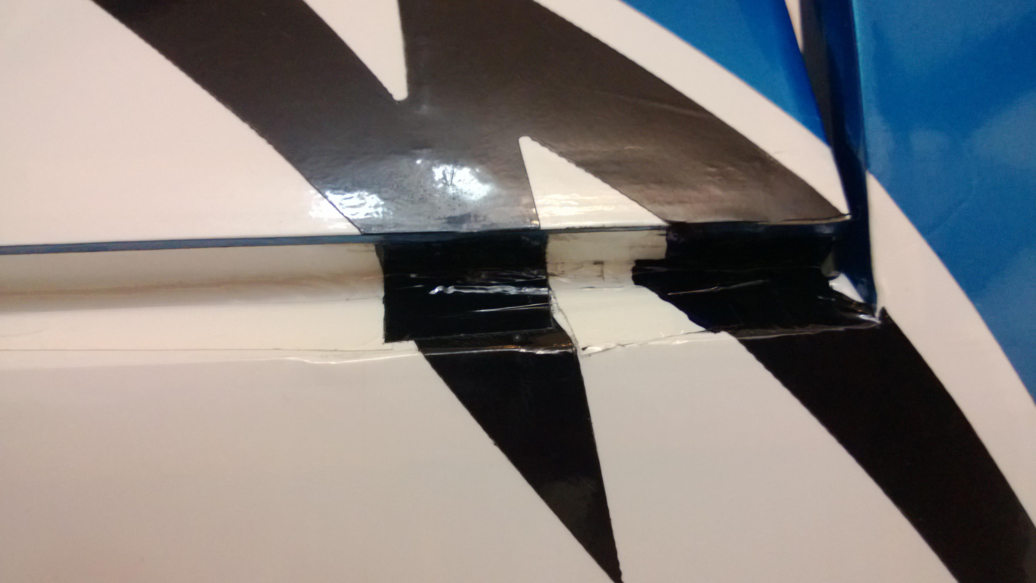
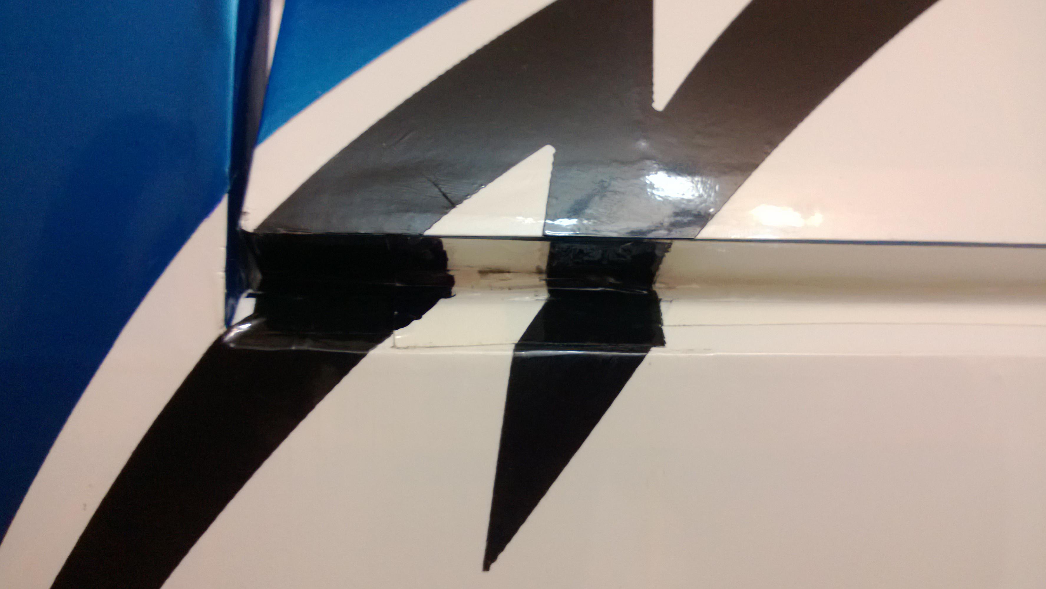
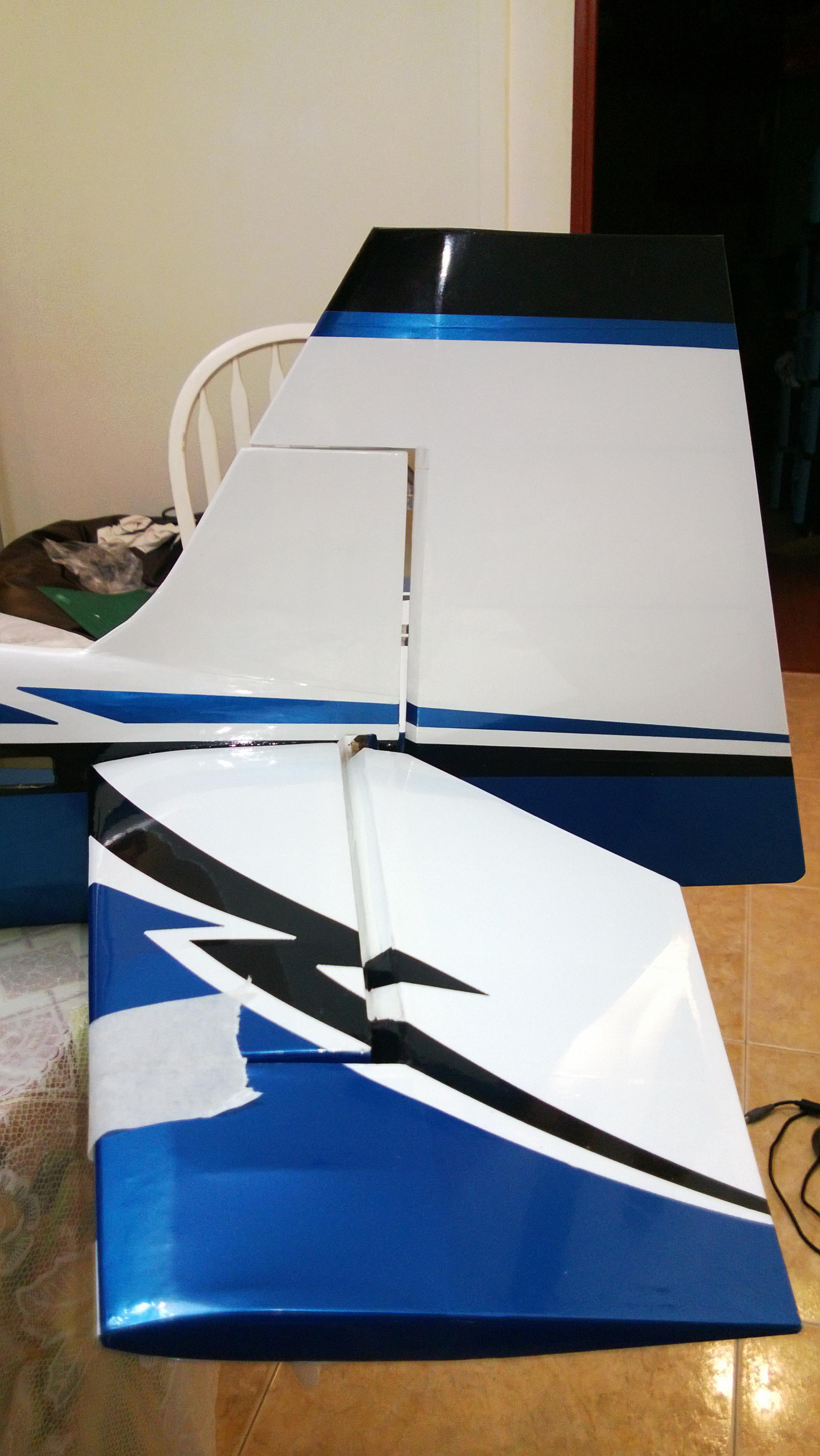
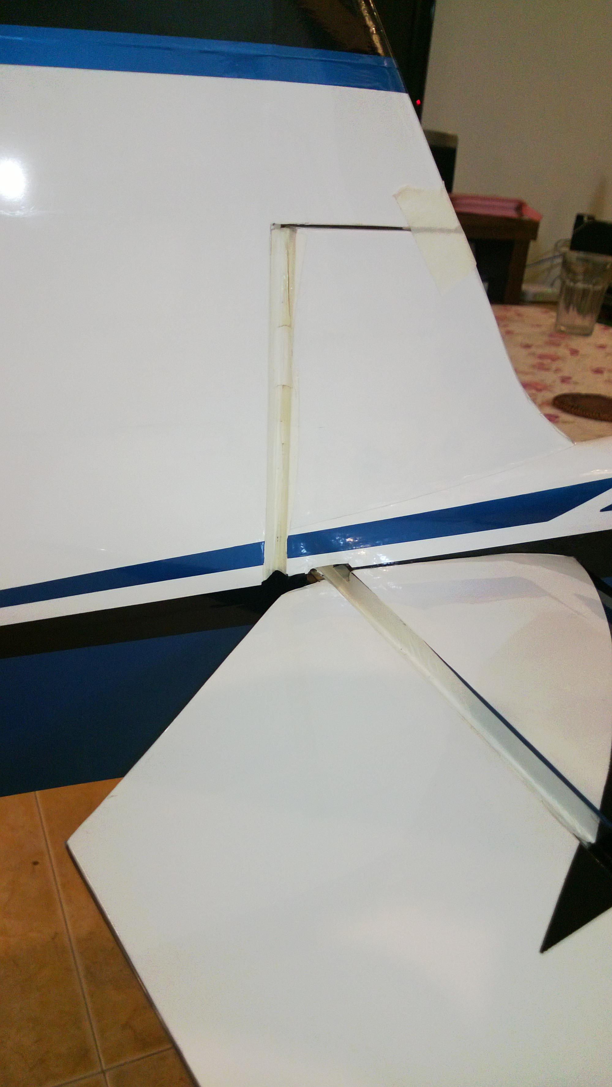
Then use CA and Hinge the elevator to the Horizontal Stab, Seal the Hinge gap with the supplied Covering. I like to Keep the same Color Scheme, Use a Sharpie if you have Too much of white color gap left.


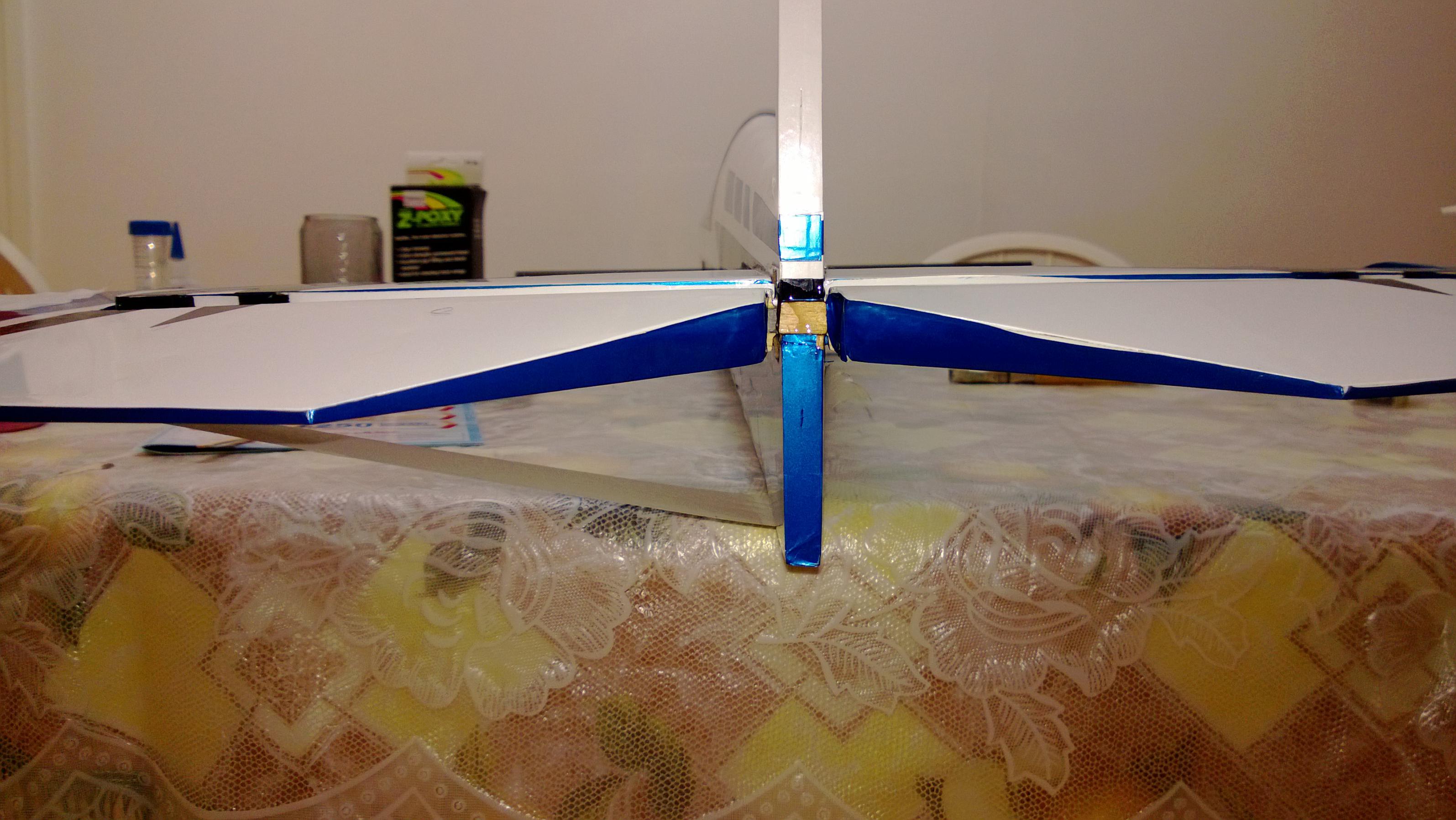
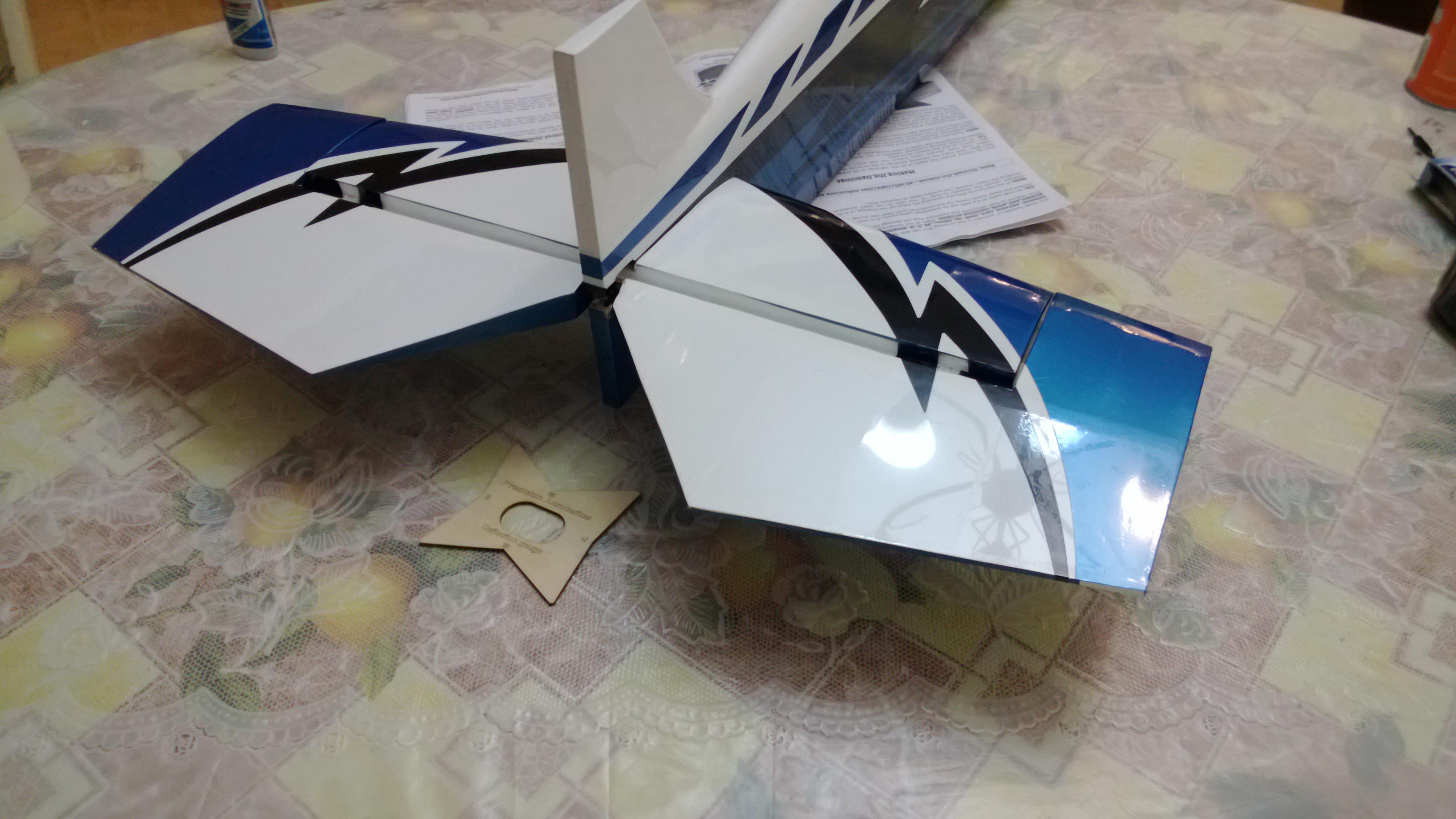
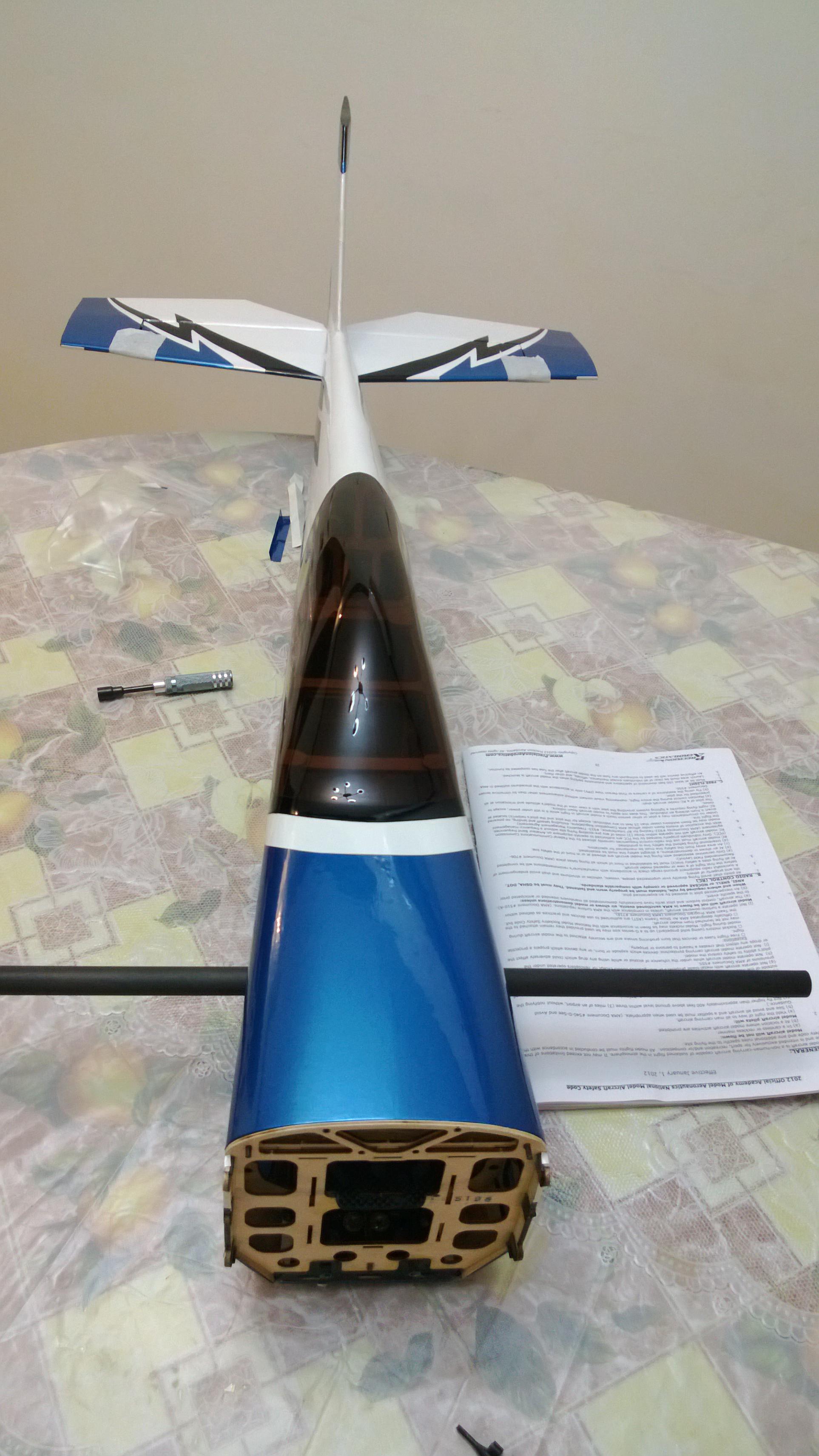
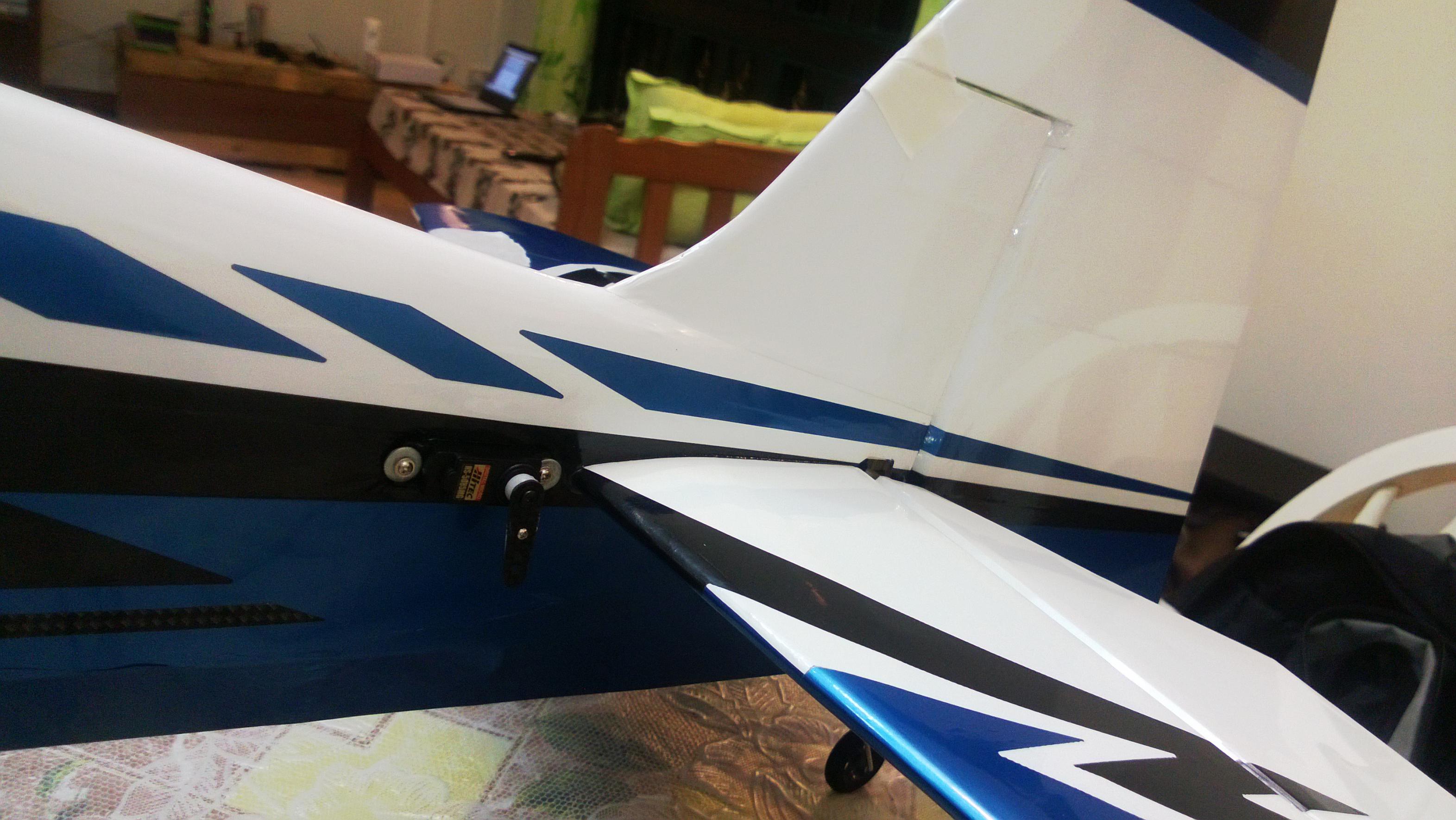
Use 30 mins Epoxy on the Stab to join it to the Fuselage , i prefer to use the 30Min Zpoxy for this purpose.You May use the masking tape to hold the Stab securely as mentioned in the manual. The final Product looked like this.


So far So good. Ensure the balsa wedge is Put in Place and you can color it up.
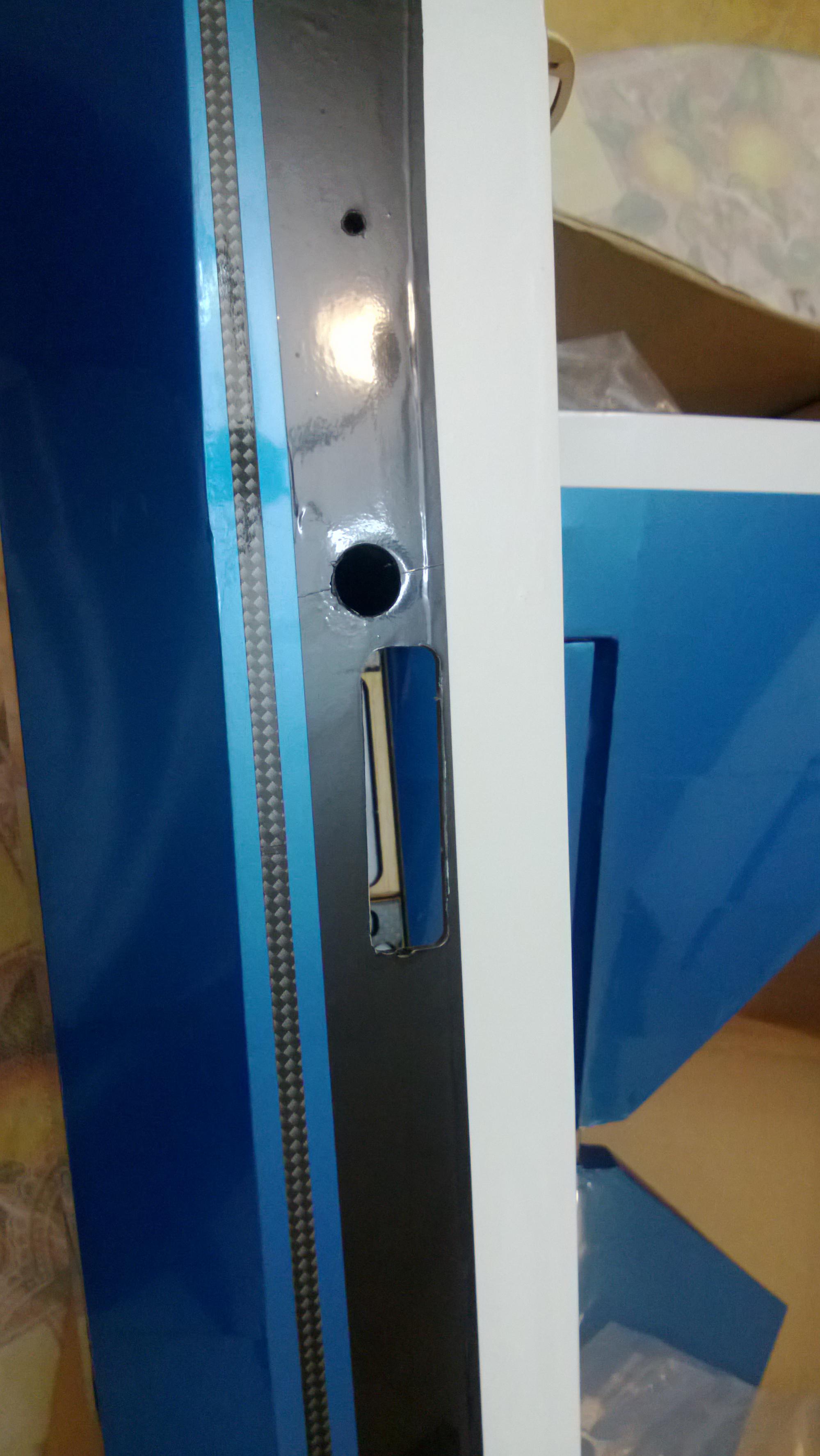
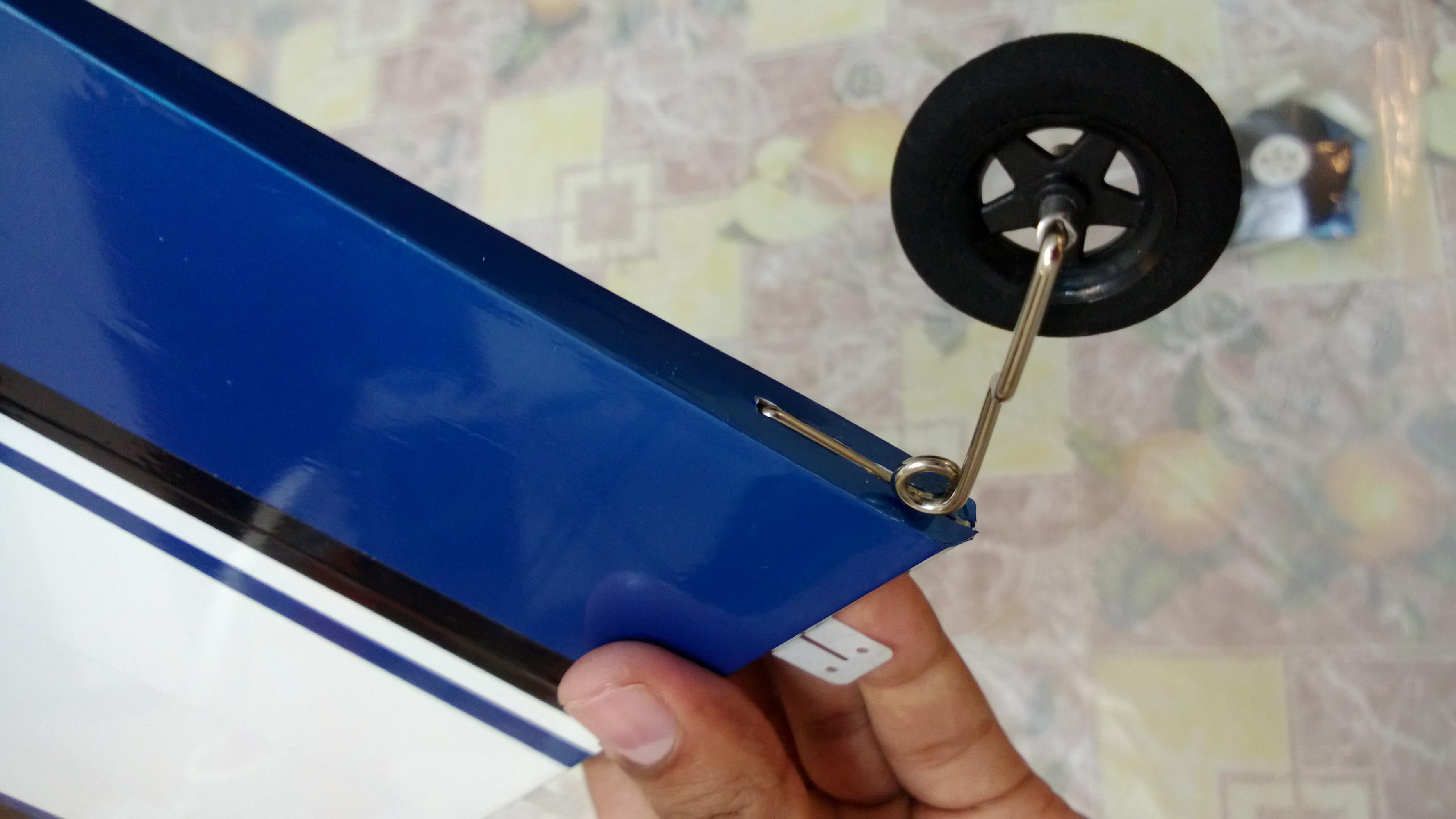
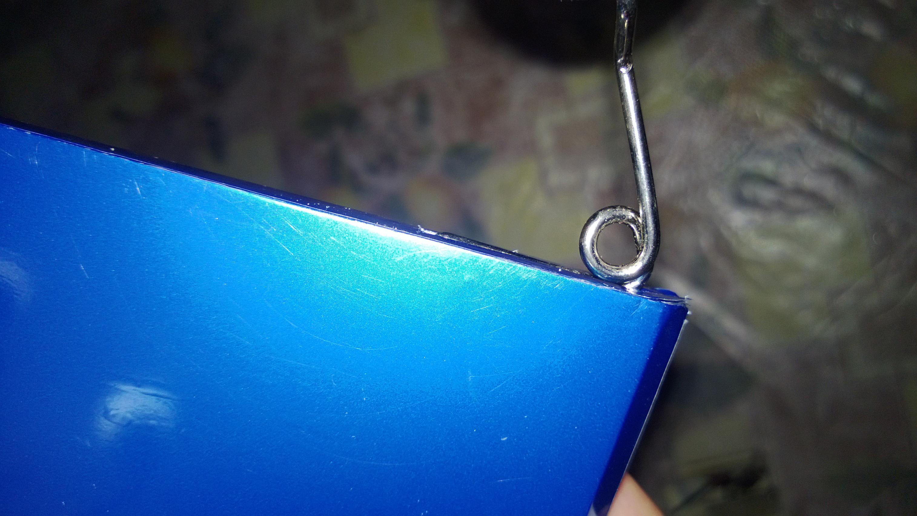
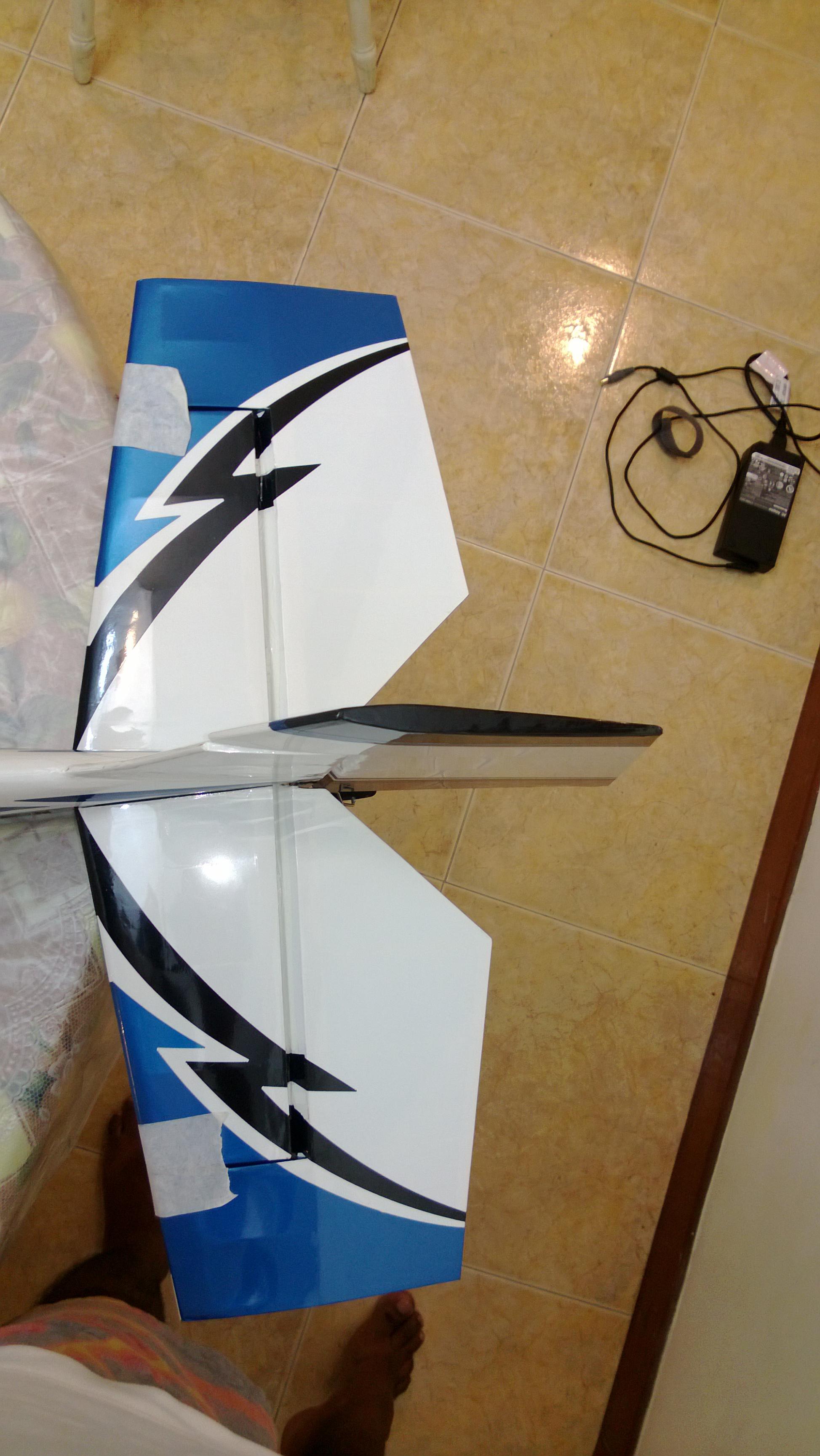
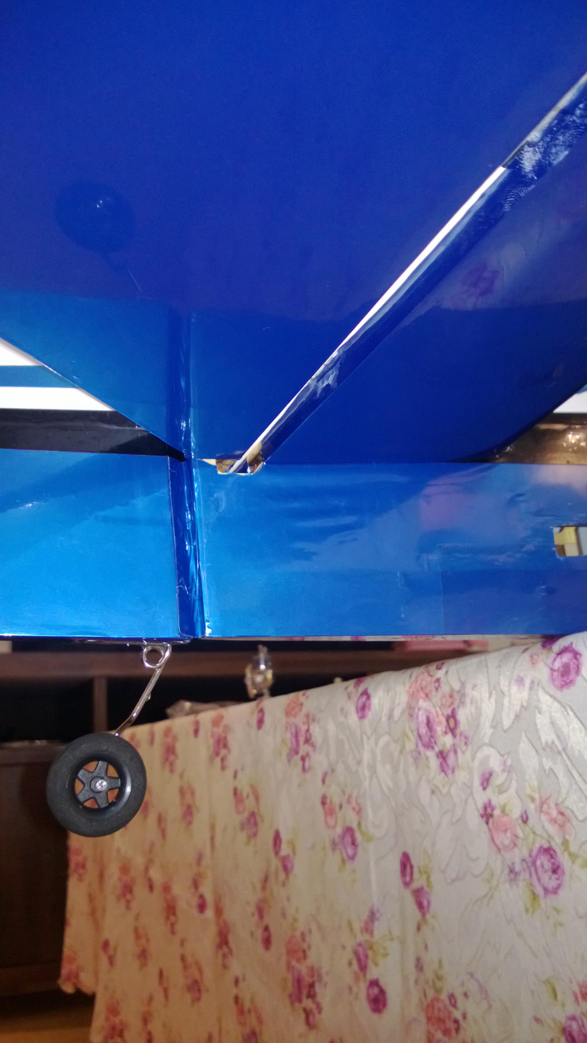
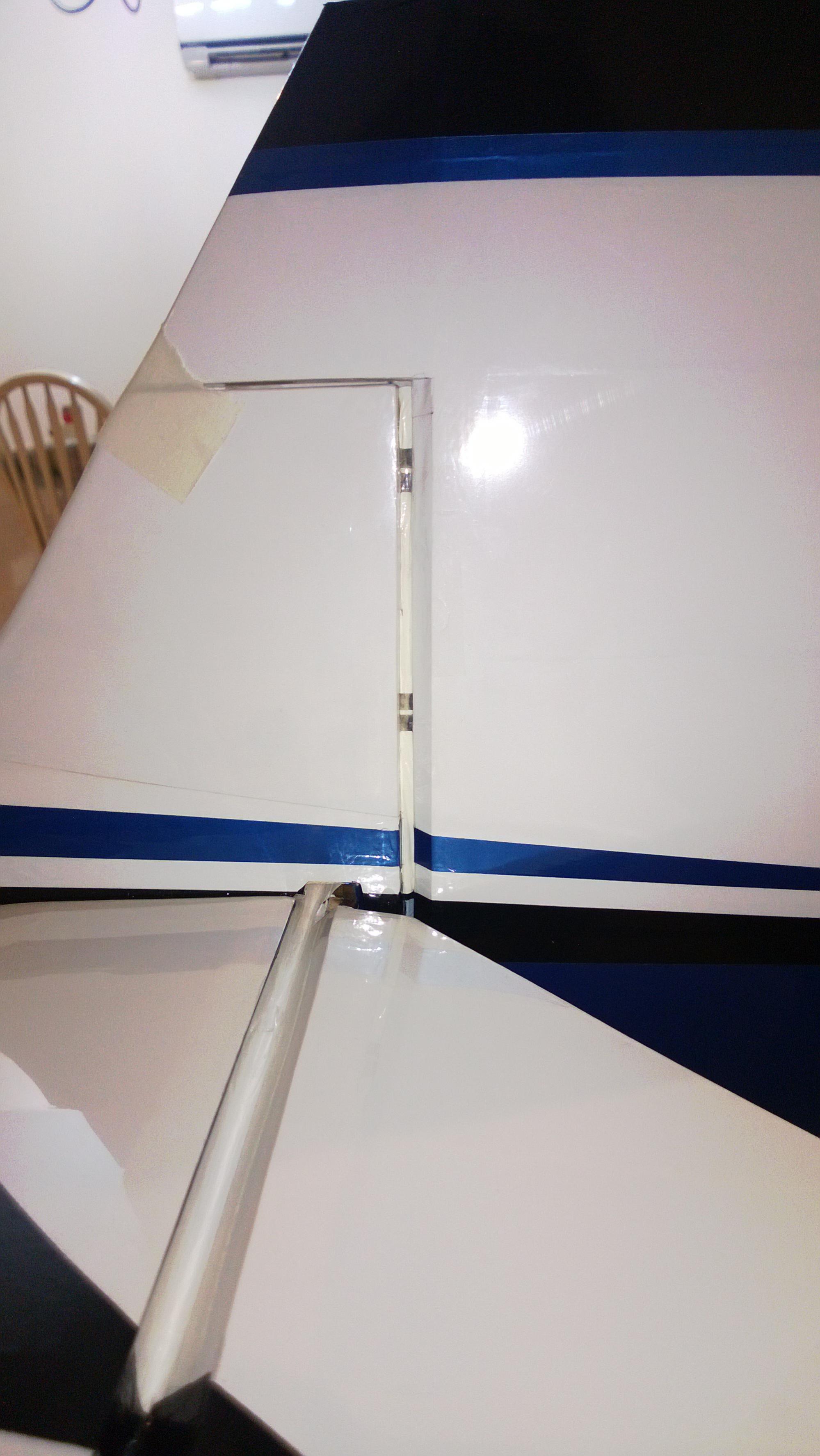
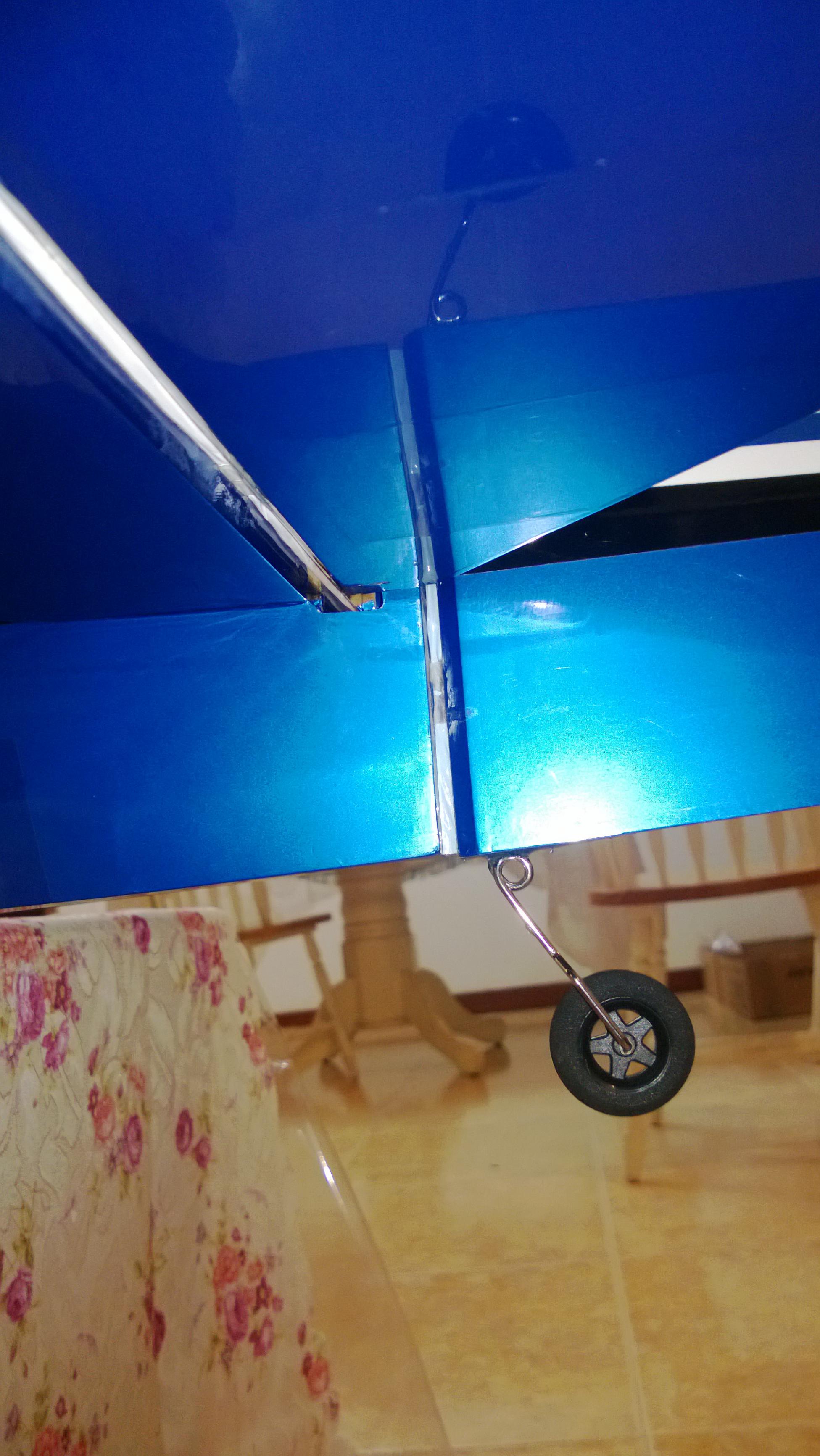
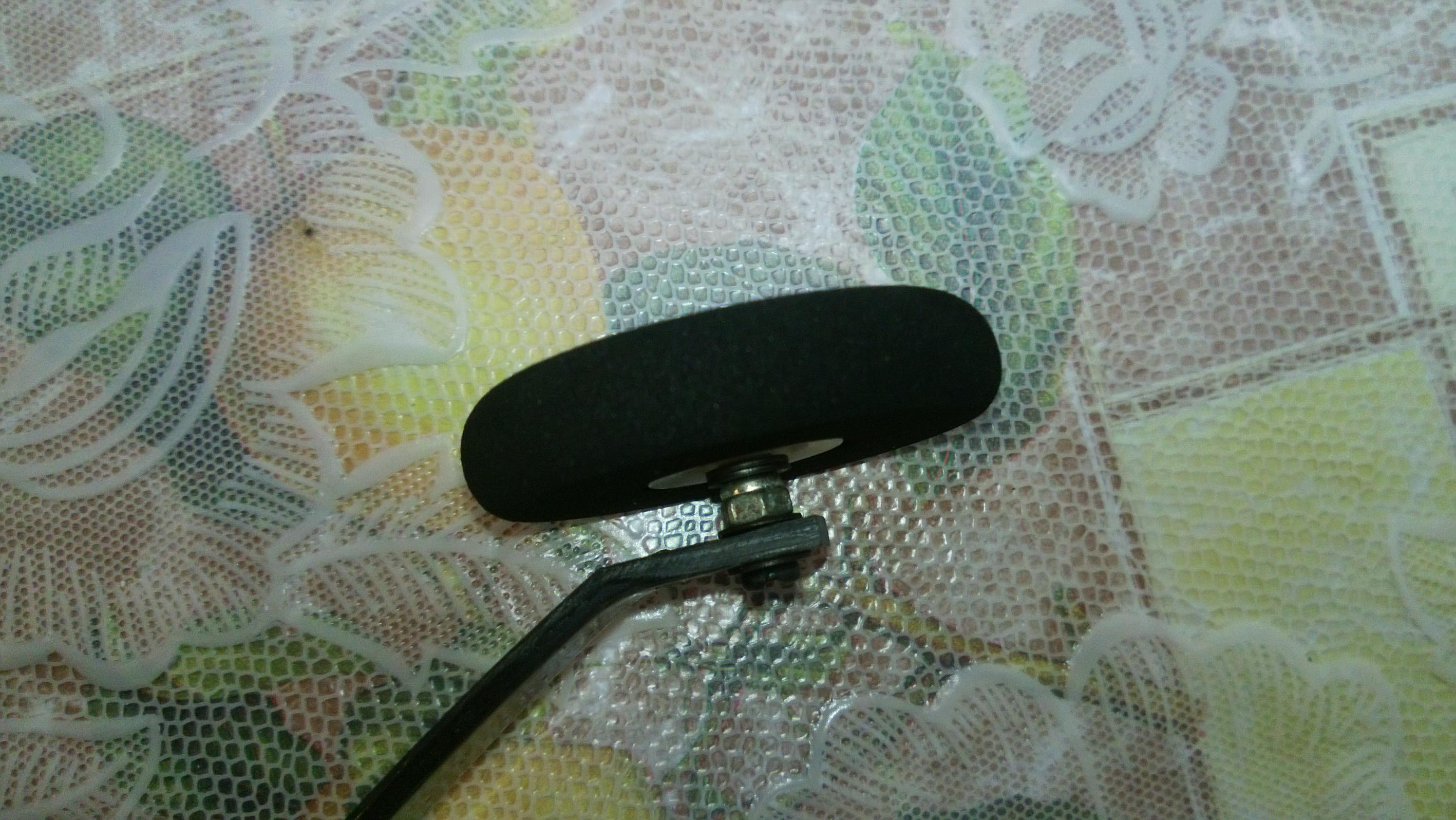
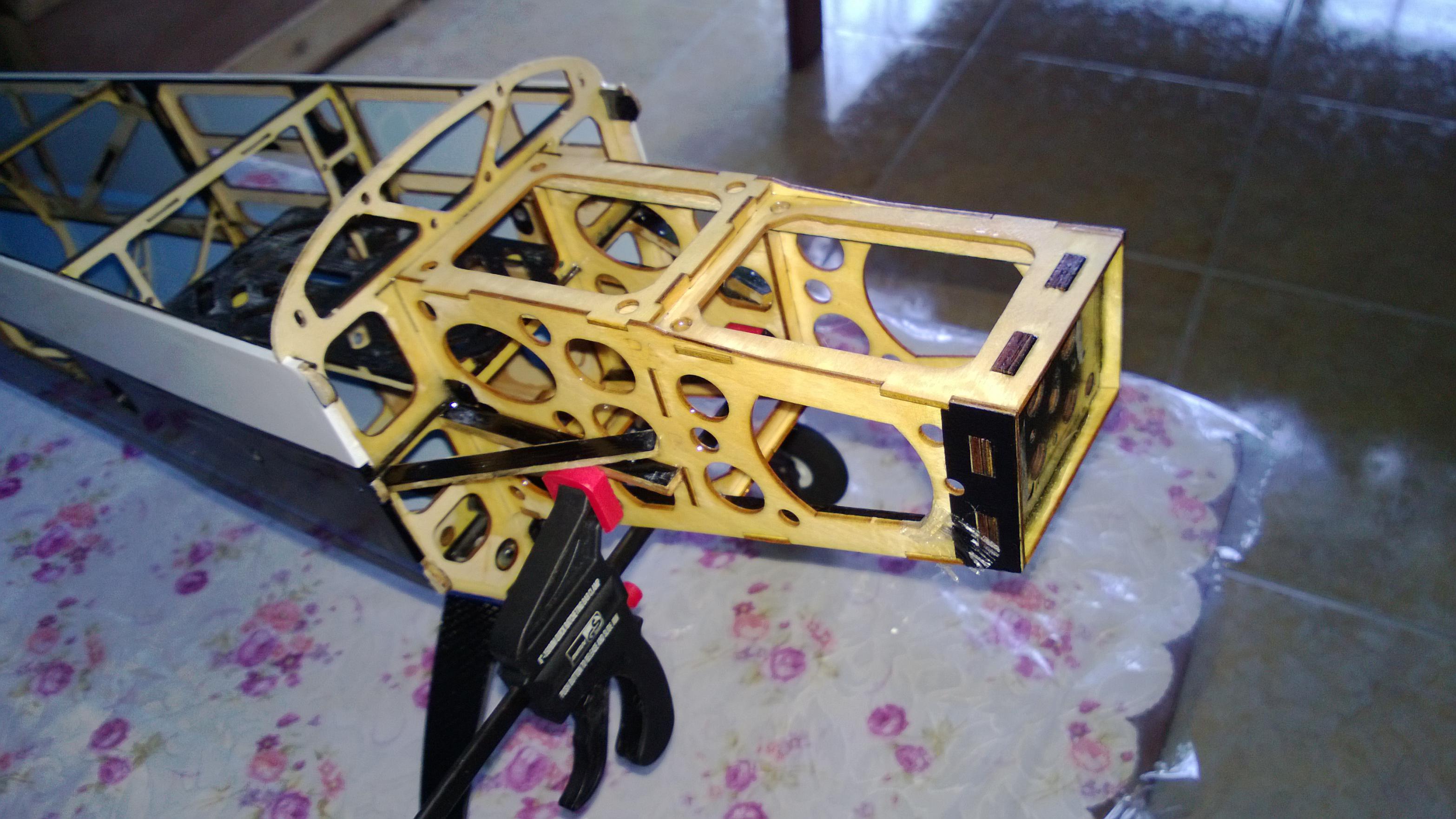
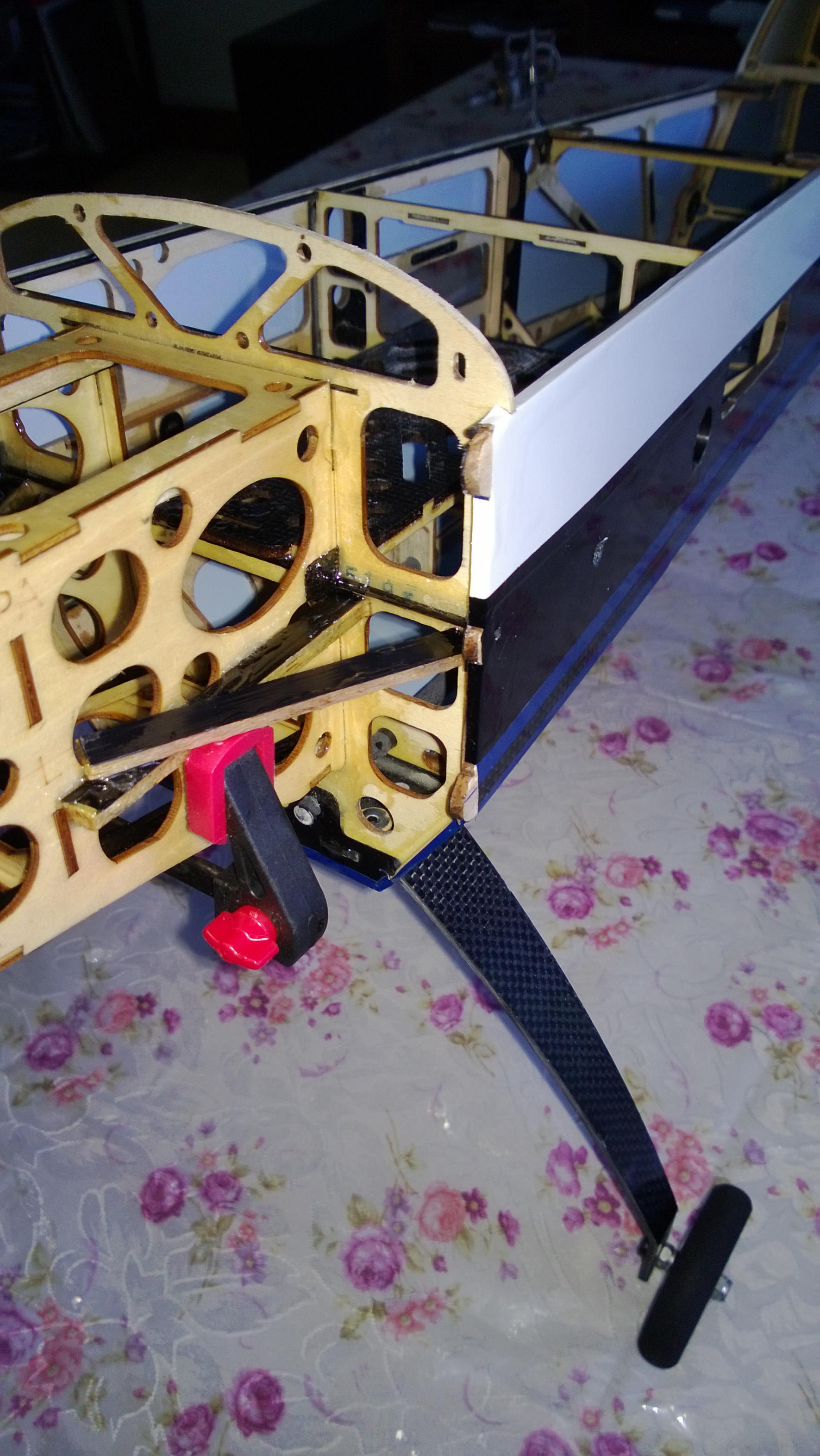
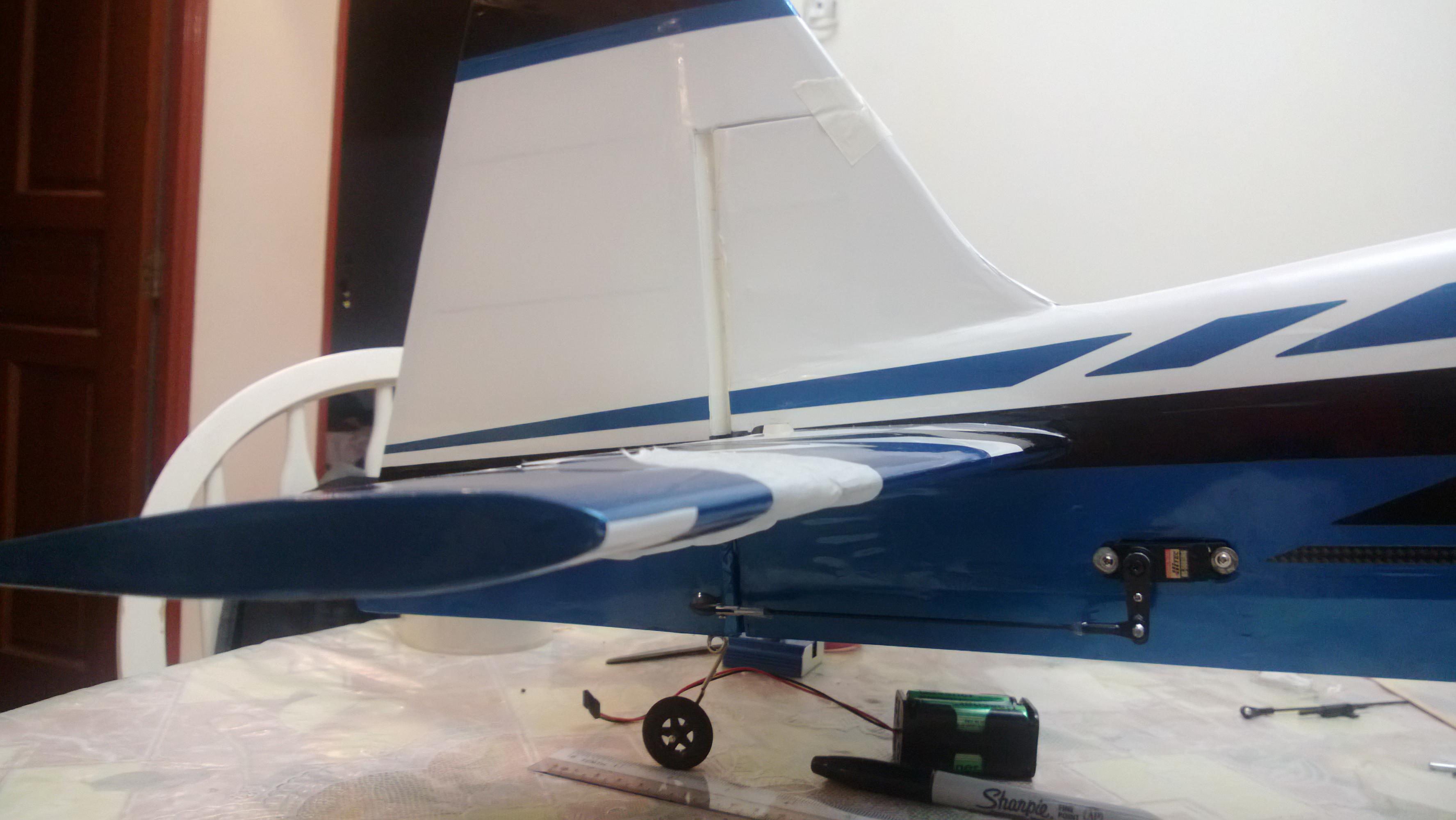
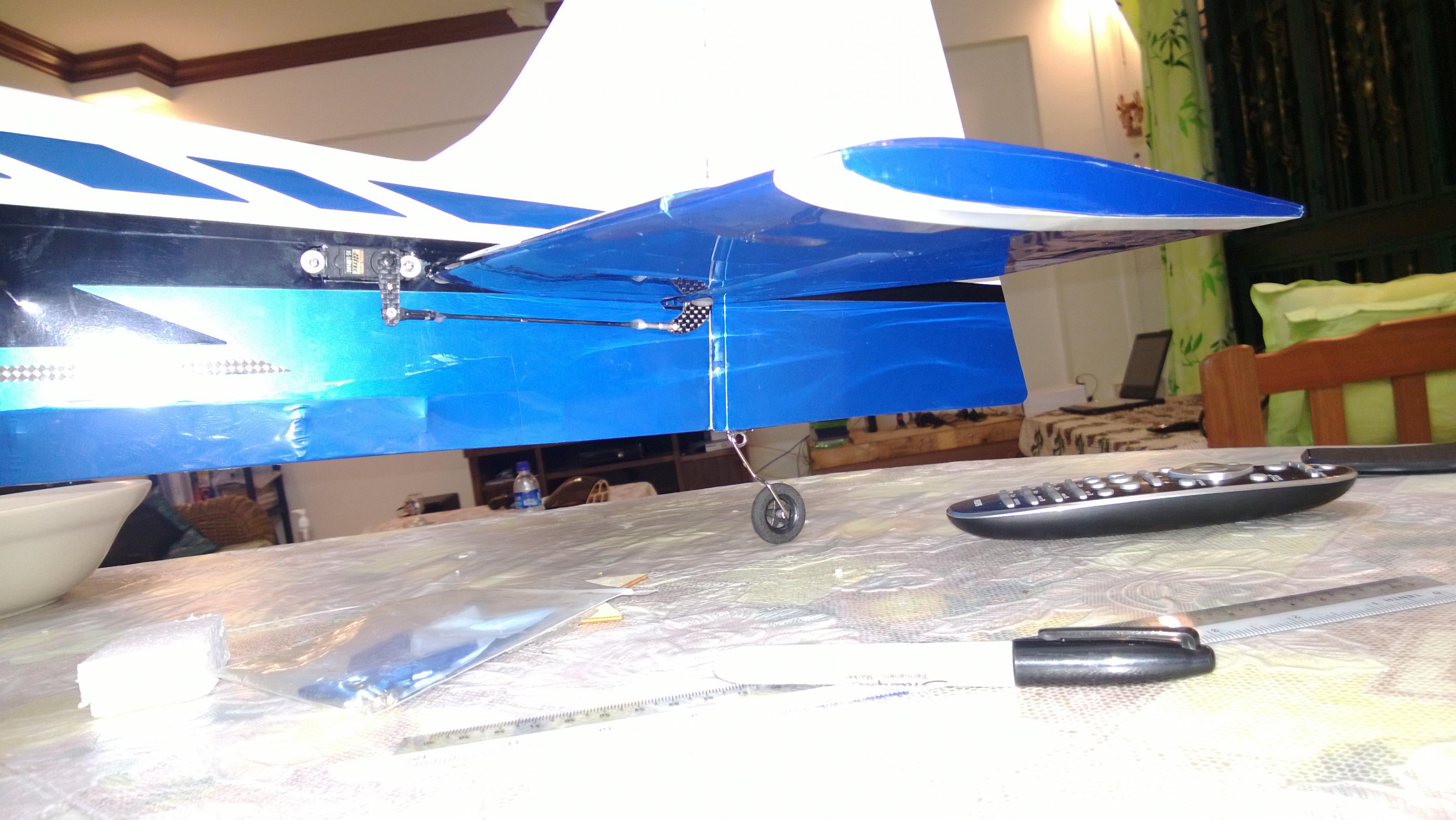
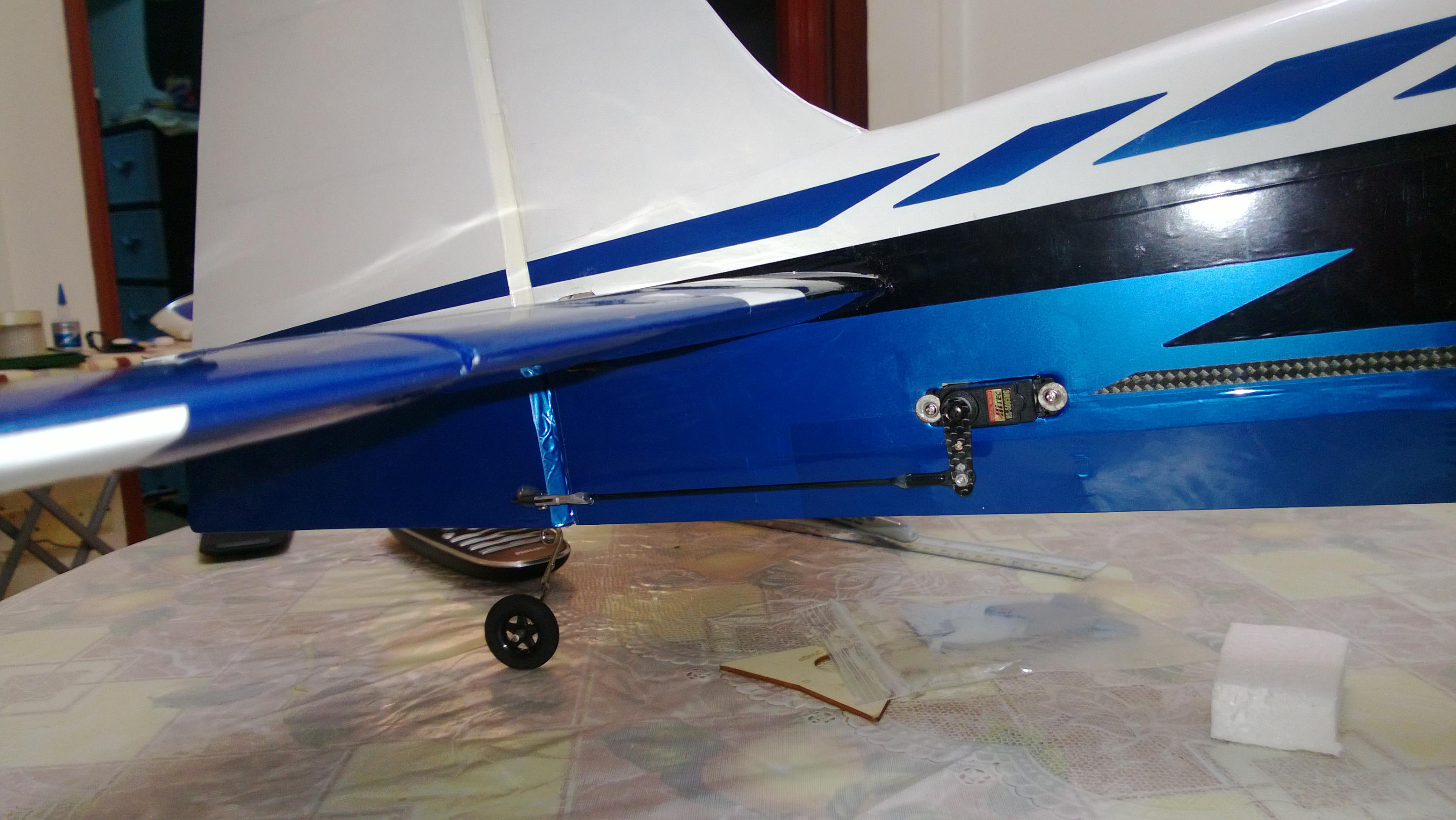
4. Now Time to attach the Rudder
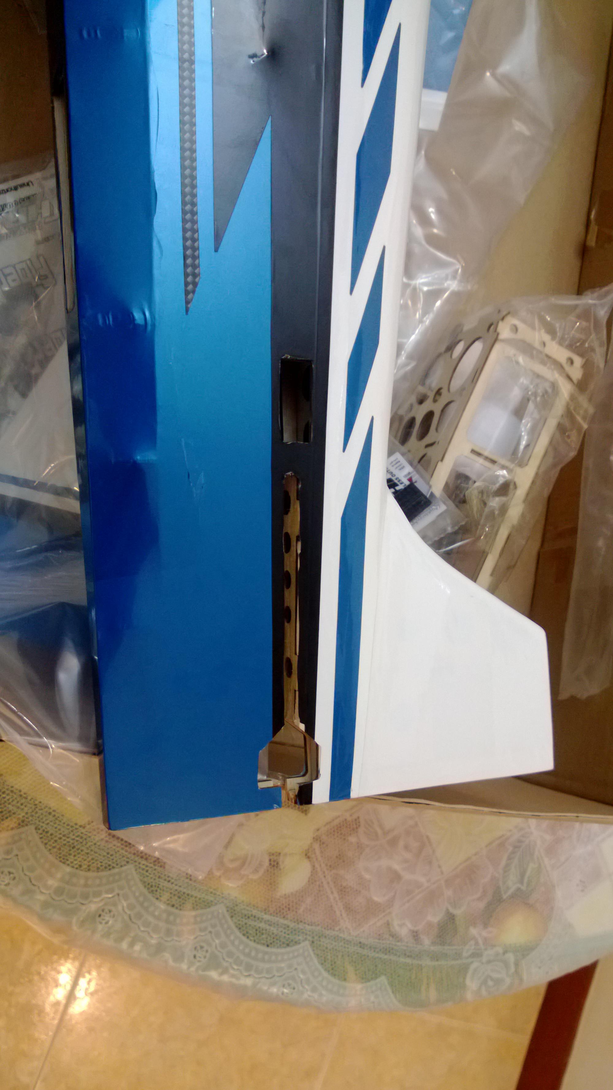
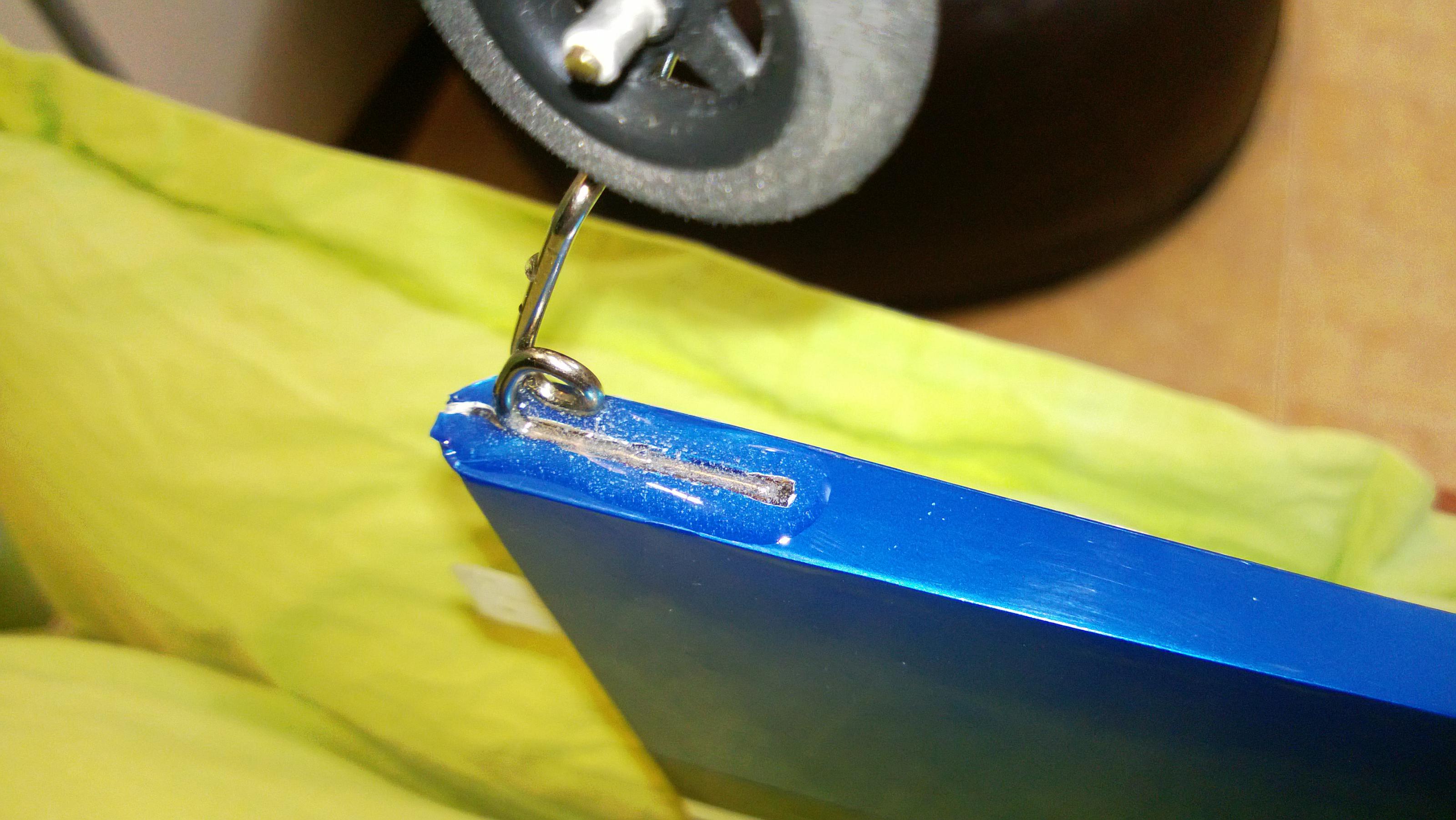
Start by putting in the Wheel, the Good part is that once you are able to cut the openings then drill the Hole, i found it pre-marked once you open up the covering. Use 30 mins Epoxy and set it aside as below. I Let the Epoxy go excess a little bit,
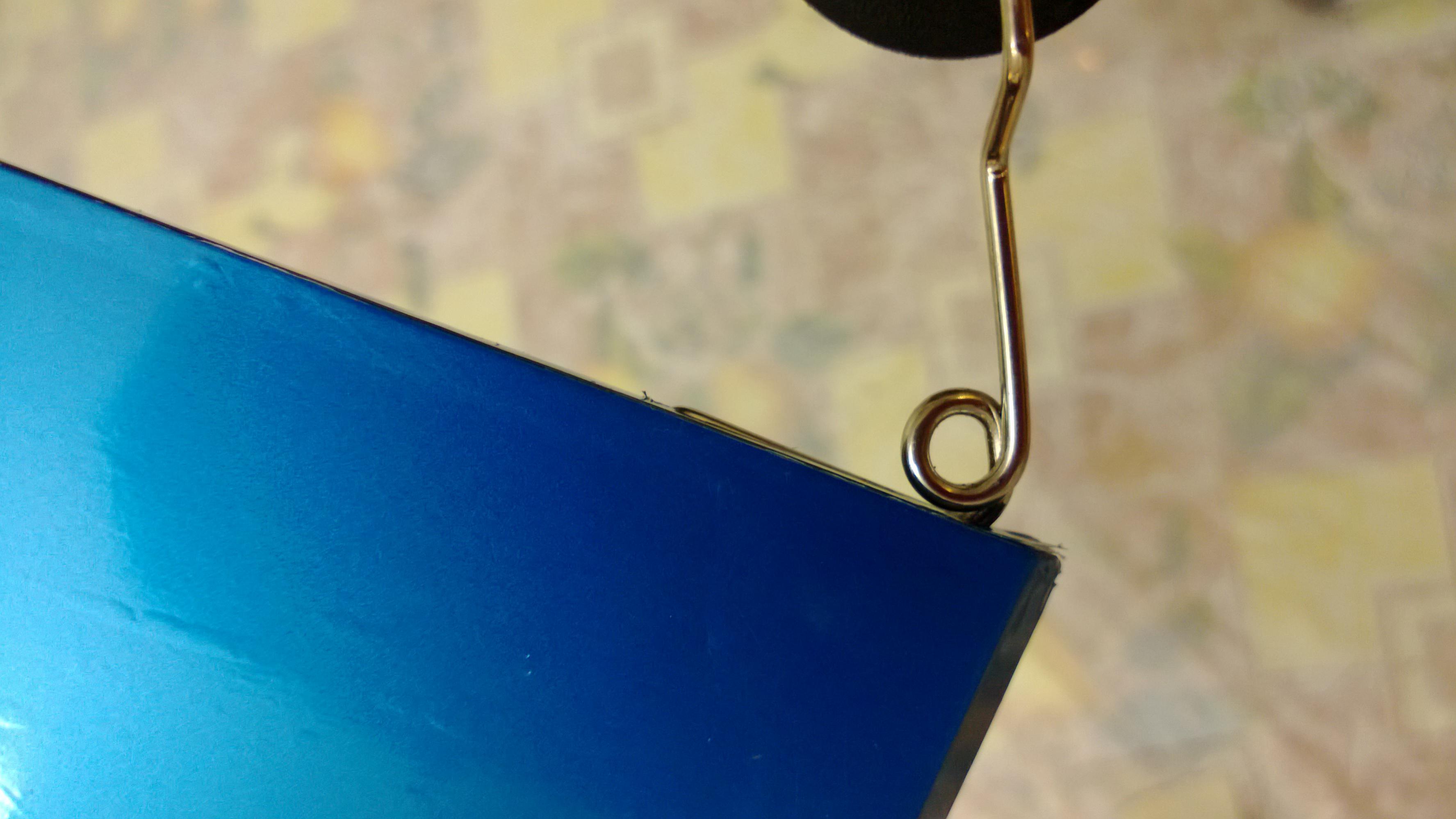
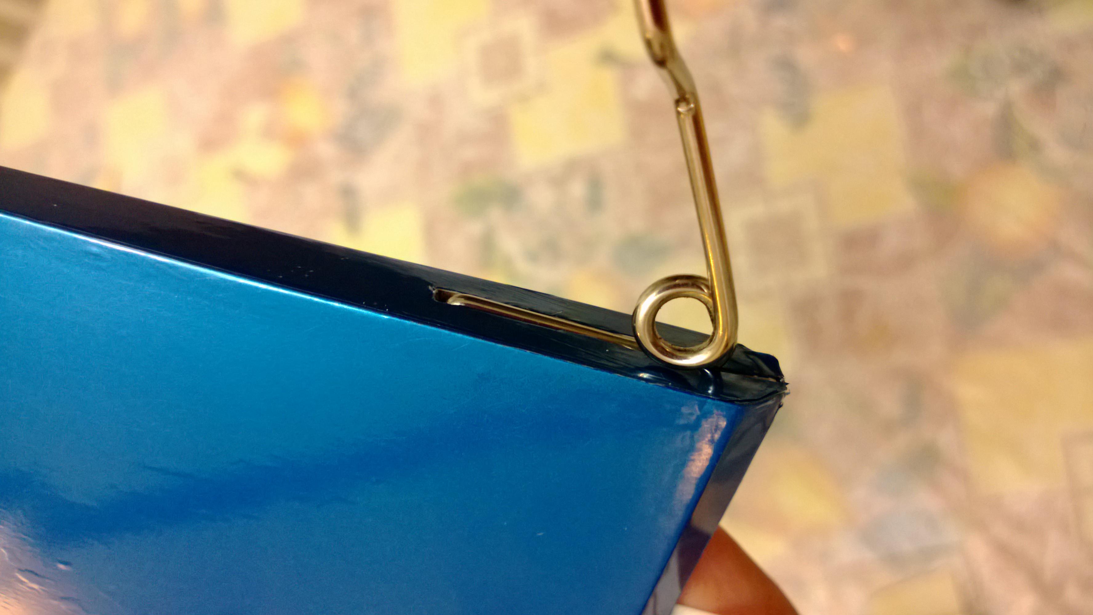
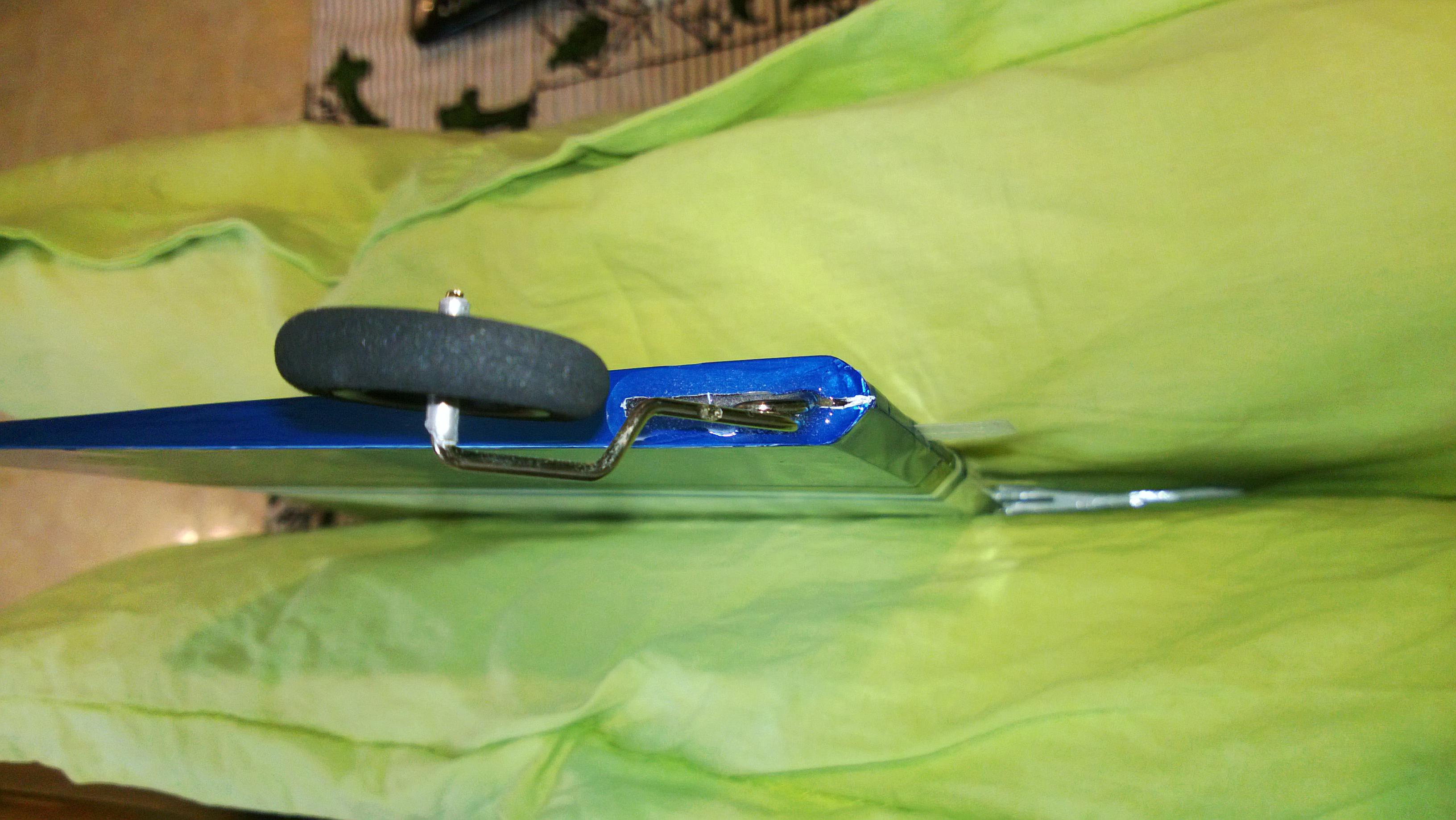
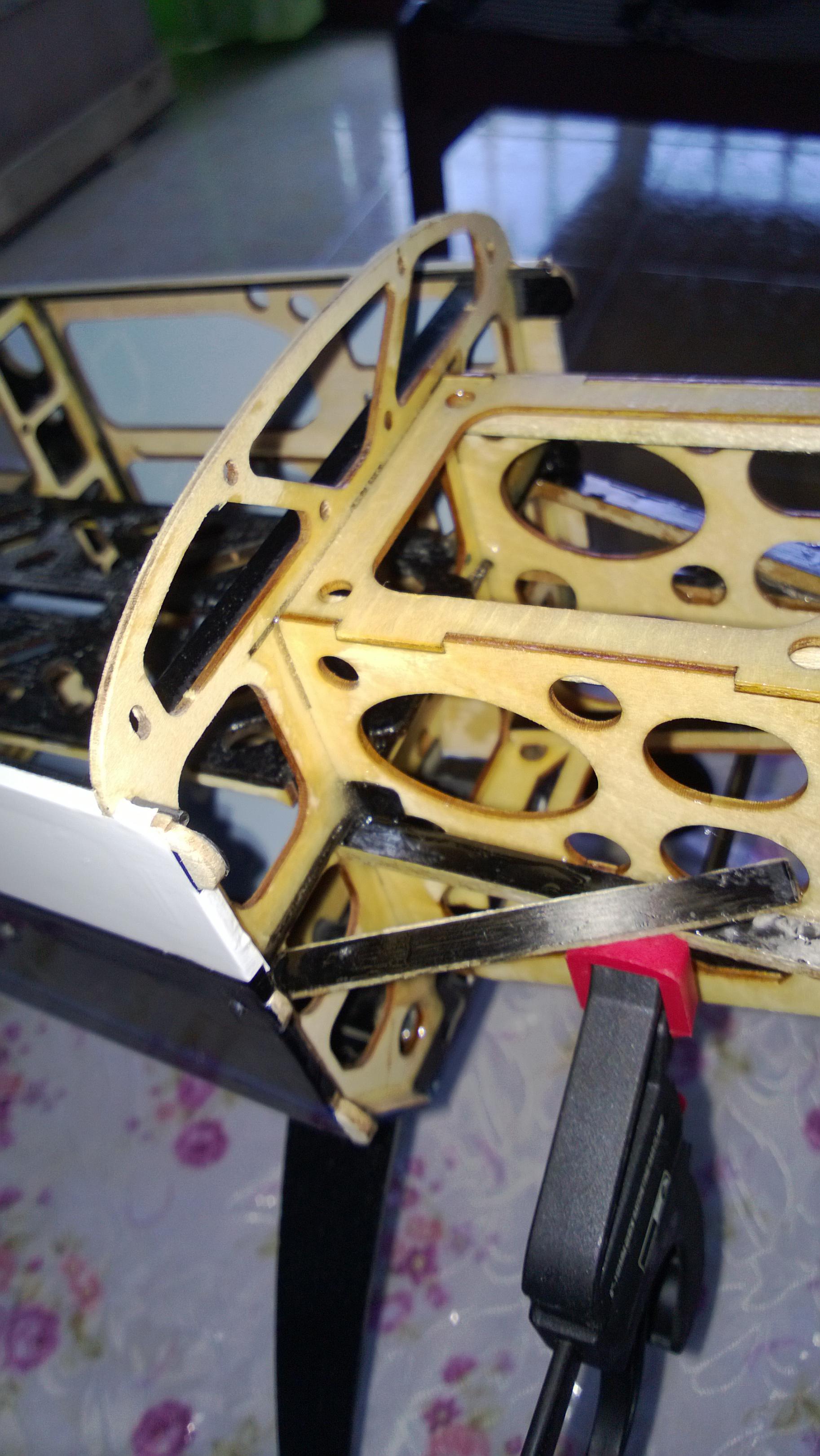
Check the fitting,


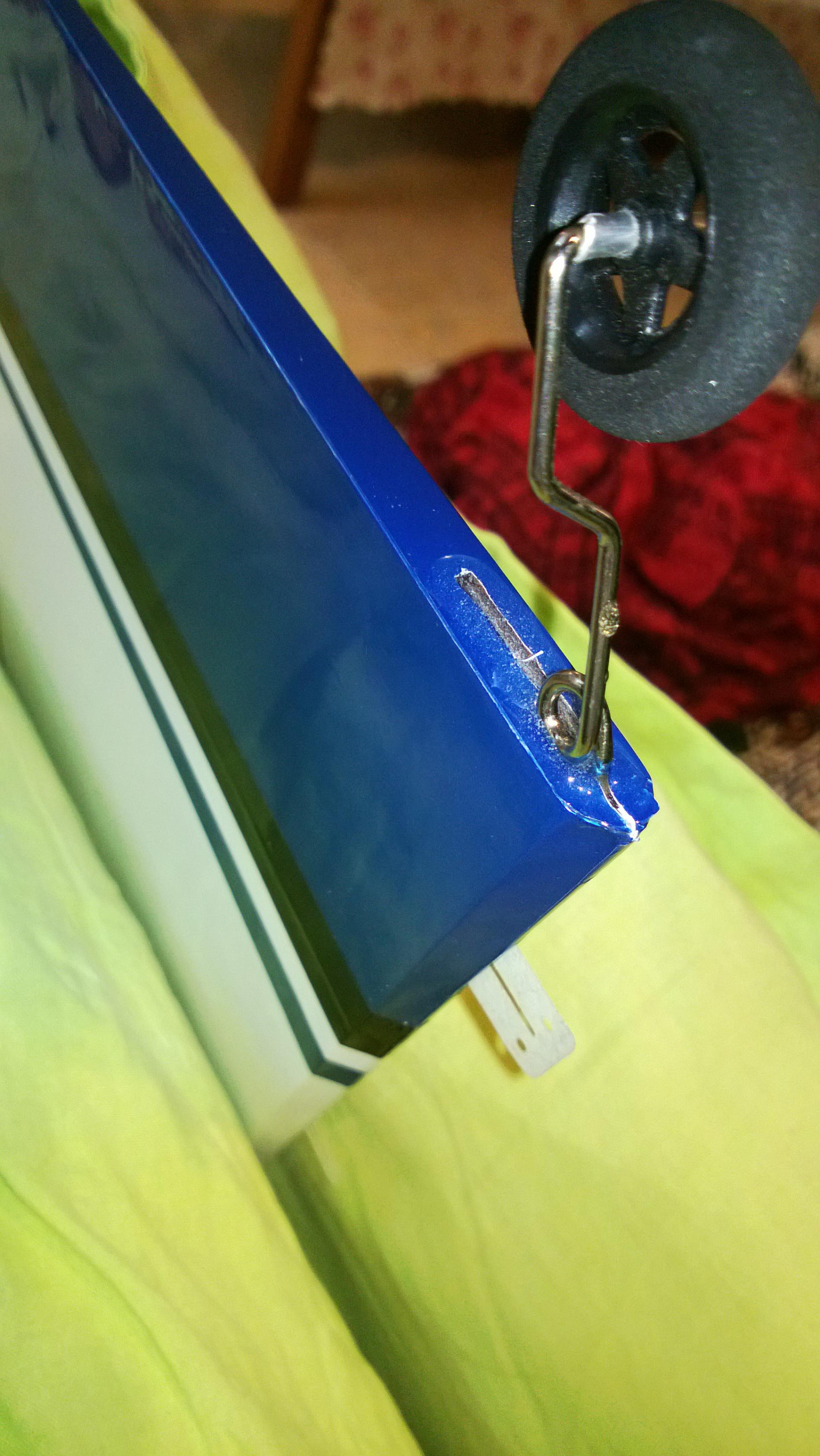
Once the assembly is complete then Hinge the rudder to the Vertical Stab and Seal the hinge Gap, Ensure you have maximum Deflection on both sides. This is how mine looked like.


I have received my katana MX From Precision Aerobatics in short known As KMX and what a wonderful plane this is, just a treat to fly. Feels like a Giant Scale model.
The Discussion thread on RCGroups is here,
But i did not find a Build thread anywhere. Although very simple and straight to build like other PA models, i thought it would be worth sharing some info for anyone who is getting this for the first time.
Please feel free to chime in with your suggestions and Build details.
I am using complete IPAS setup as recommended by PA for this plane, Details can be found on there website.
First Look at this plane and i can tell you i loved it. I own the PA ExtraMX, AddictionX, katana MD and Bandit (Still in box).
Seems like there is quite a bit of improvement from the ExtraMX construction :-
- The battery tray comes up unlike going down in my Extra MX this to me seems like is a big change to save the balsa near the LG area from shattering and breaking during those not so soft landings. ( The KMD has it this way). My Extra MX does have the cracks all around here over the period of time.
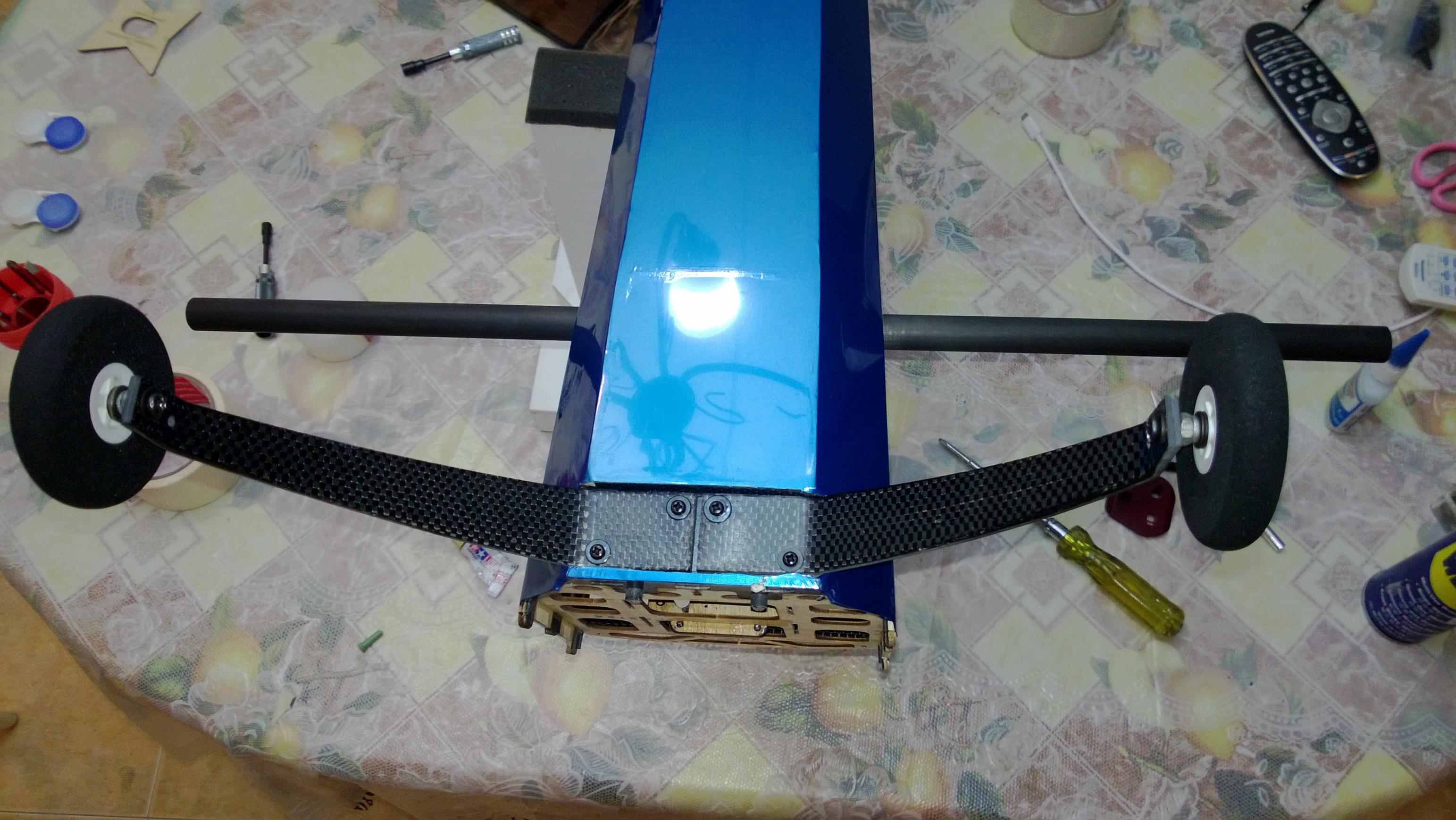
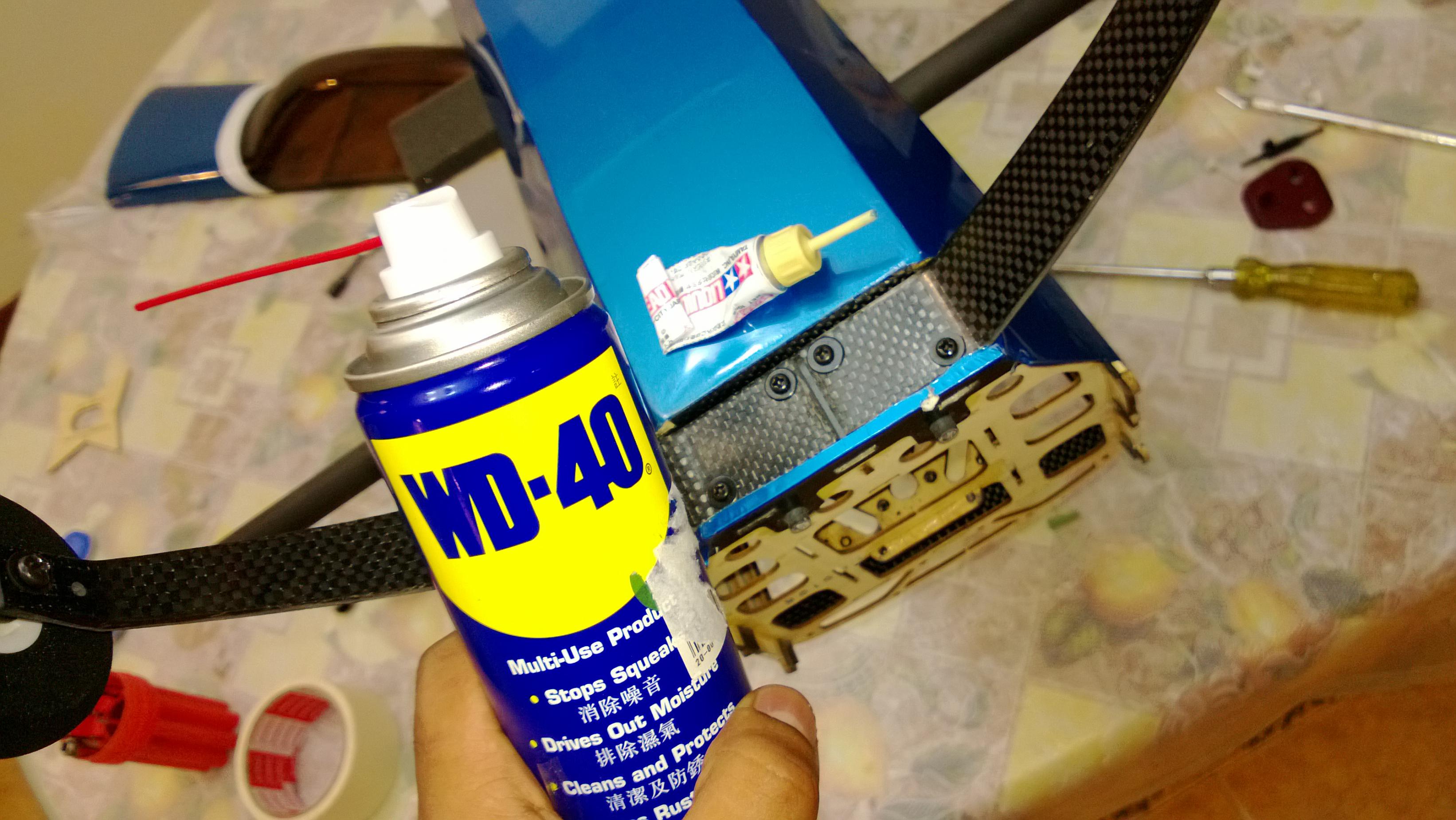
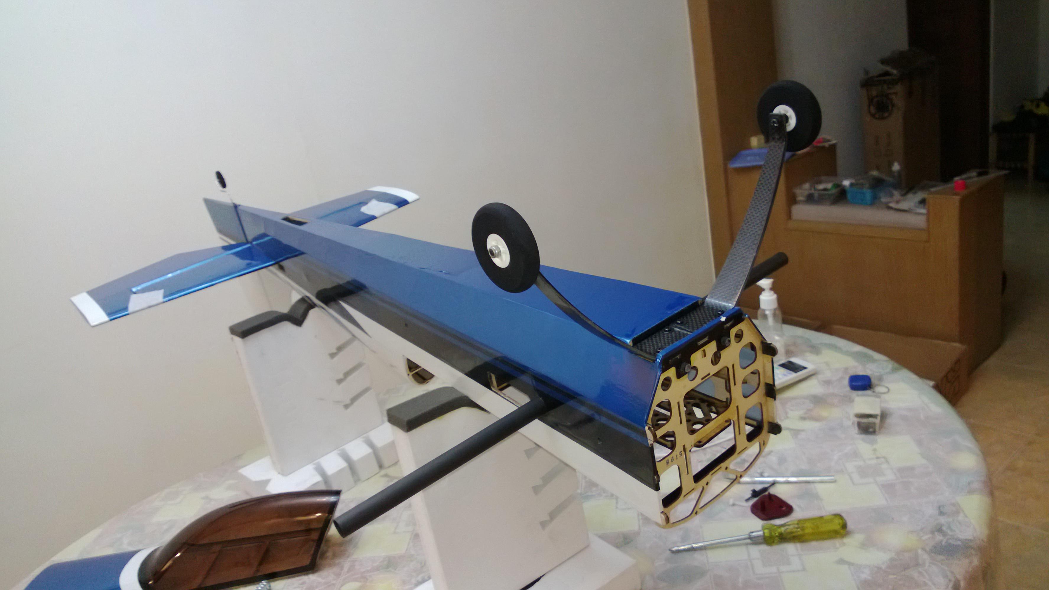
- Loved the alignment of the motor box it fits just right on. In my case the holes for the center CF rod were there I just needed to tap and open them up.
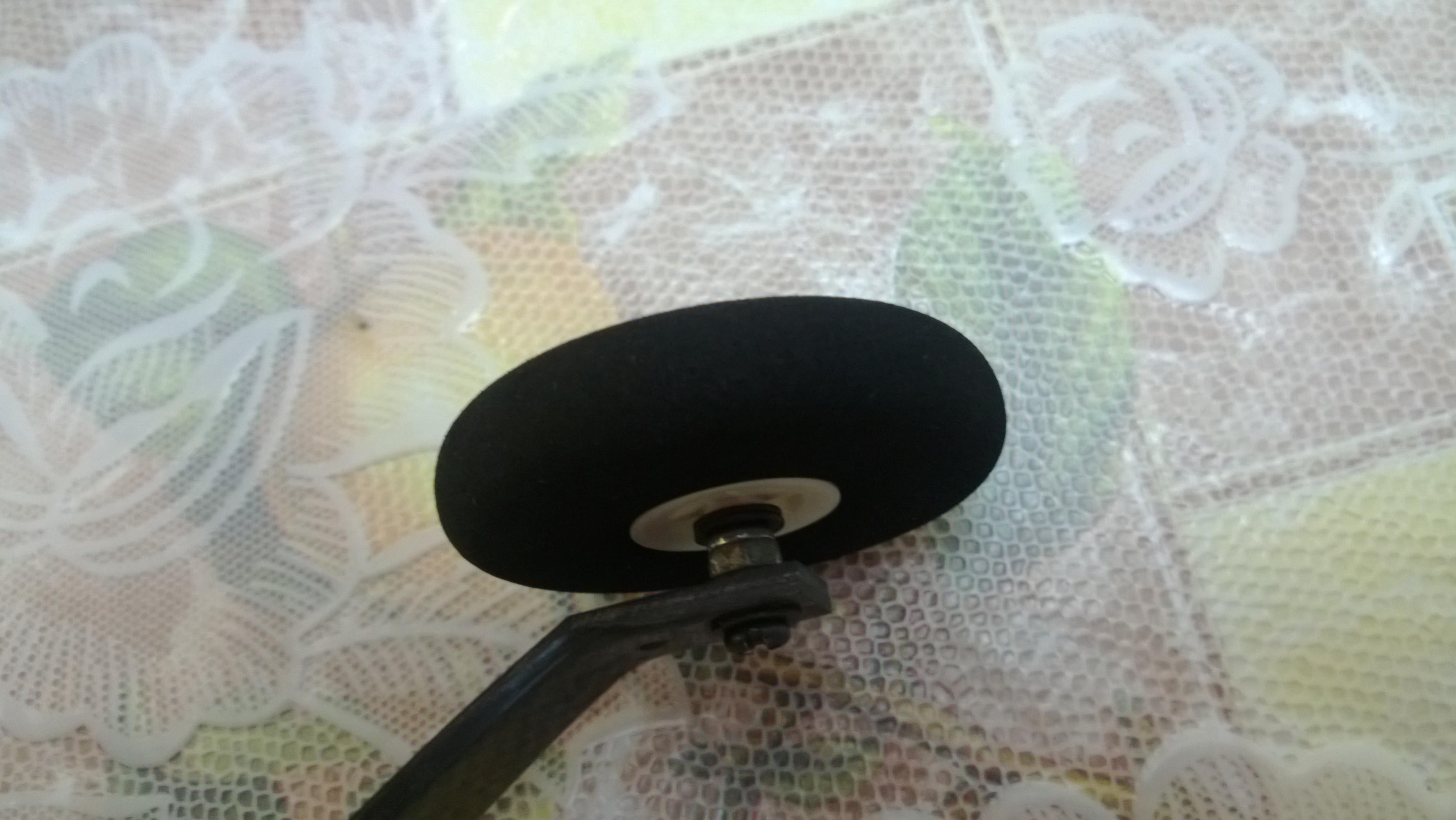
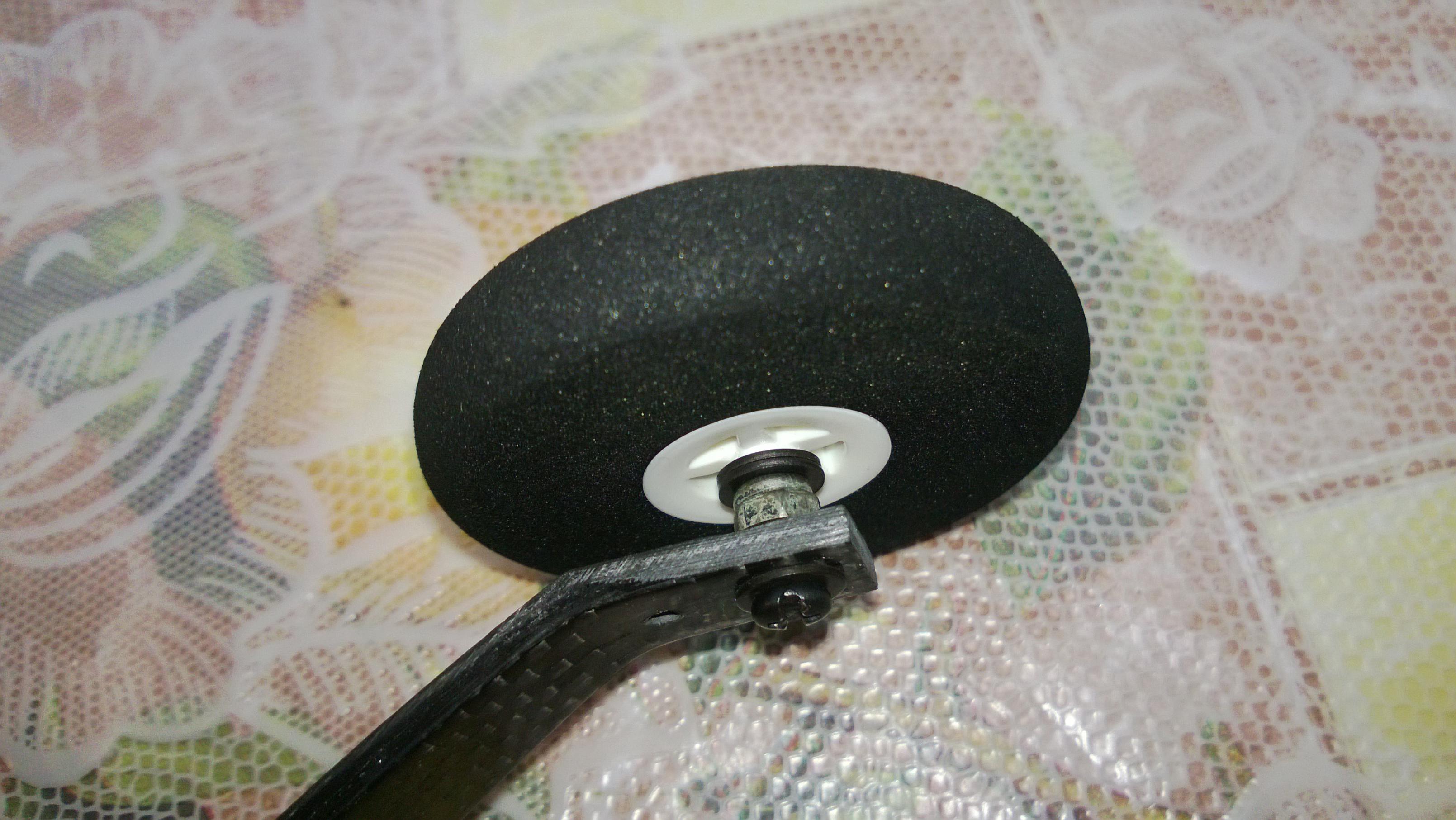
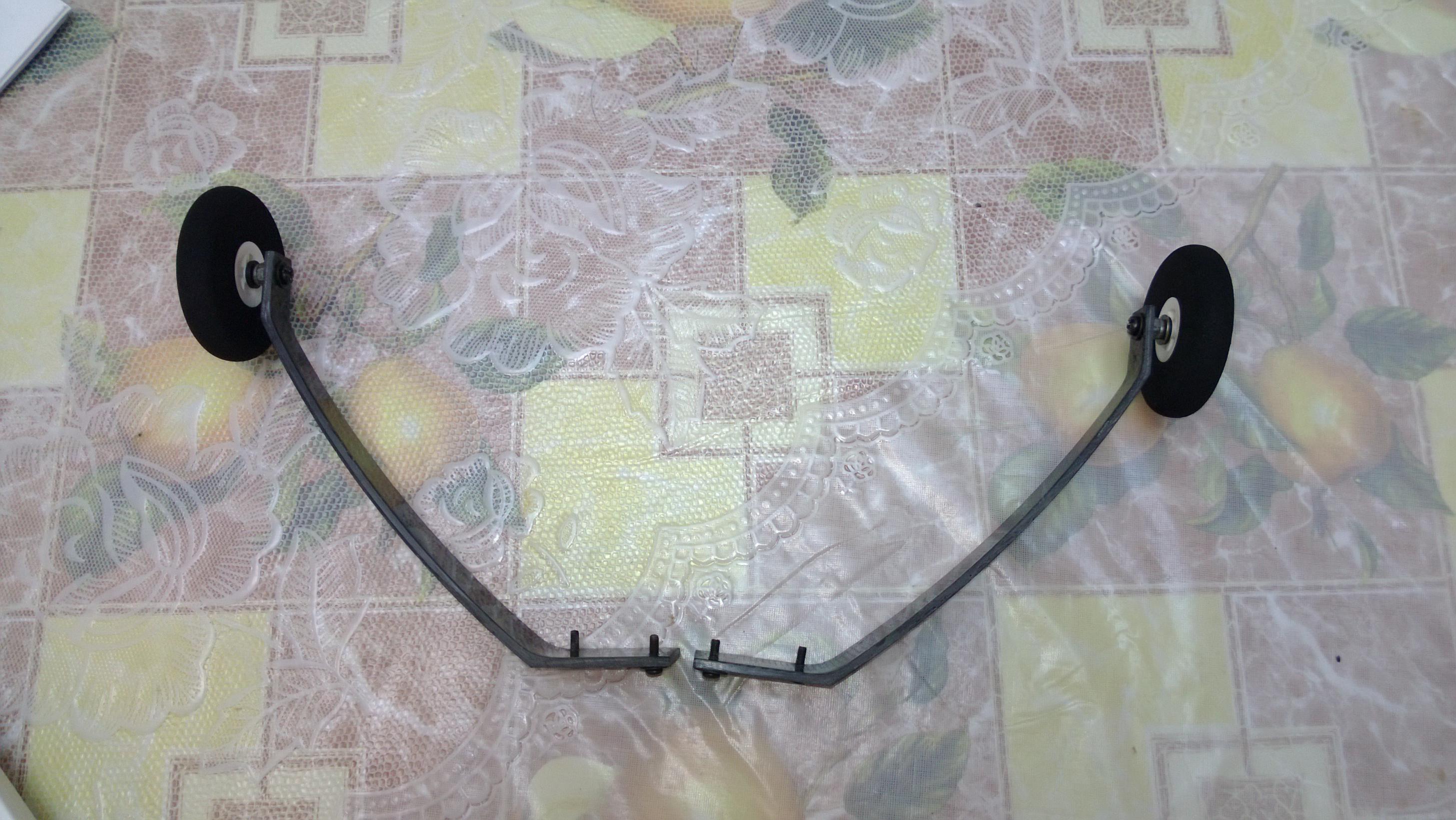
- The Landing gear Screws went right in without being a tight Fit at all and very easy loved the fitting unlike the KMD where the screws protruded out.
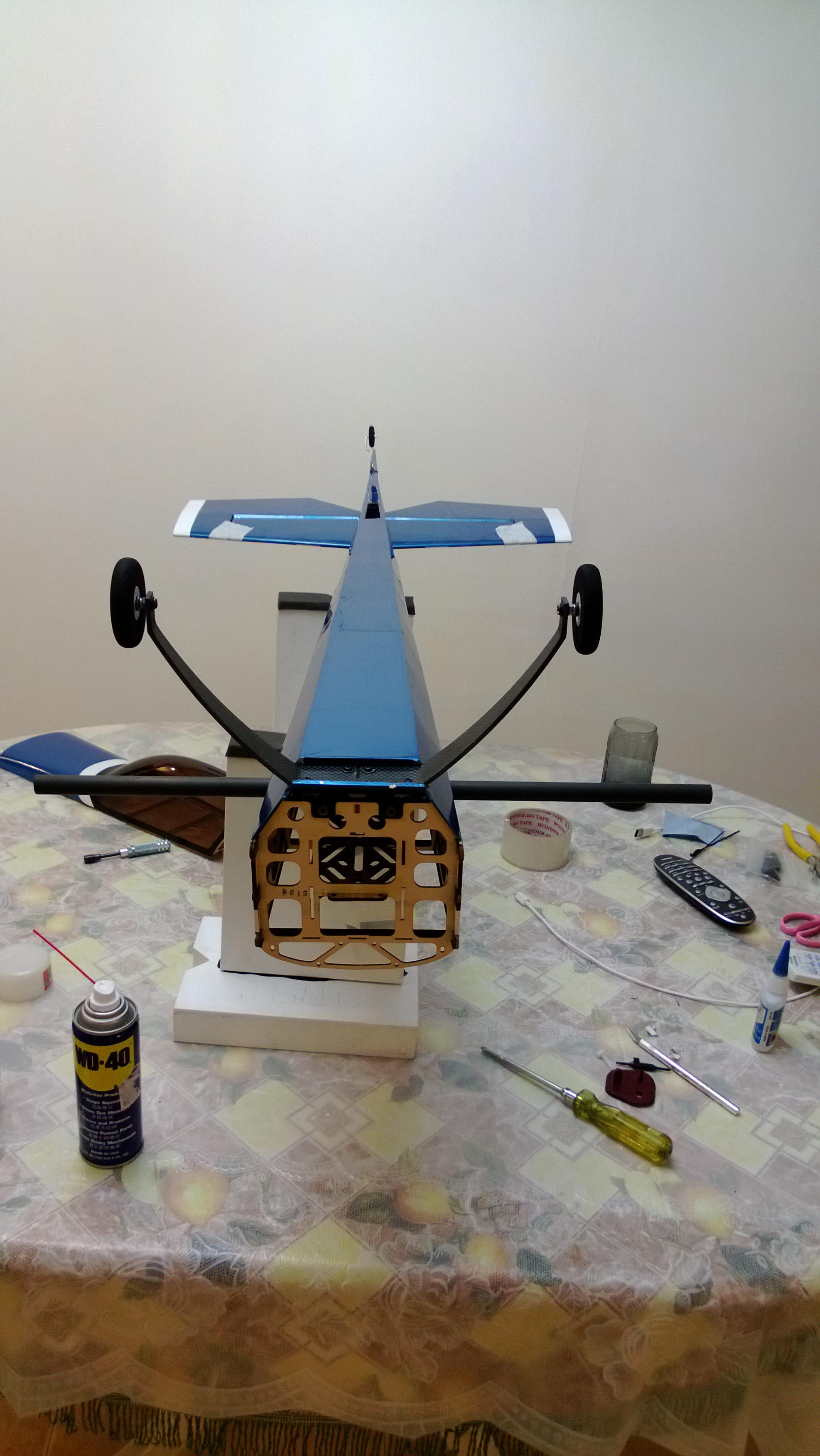
- The Rudder wheel base has been properly cut out and I jut had to cut the covering a bit surprisingly seemed like the marking for creating the hole for rudder wheels were in place.
- The wing CF rod went just right in without needing to be sanded.
- Did not like the way the VG’s go in there, should be a better mechanism of getting the VG’s 1 out of the 3 VG’s did not line up the way. It was a little tricky to get them in place.
- The cowling seems to be a tight fit and took me quite some time to get it aligned, I guess one should spend a little bit more time to get this one right or may be it was just my piece.
- More to talk about as we move on keep reading
..... The rest of the Fiber fusion is just perfect on the spot like other Models.
Here we Go, The box should look something like the below pic , I opted for the Blue one as the color Scheme and visibility is Just Brilliant.
There is a nice video of what you can expect in the package, here.

My Pic does not show the Wings they were outside the box , But you will see them soon.
I followed the manual Completely and i recommend any one who is starting the build to first go through the manual thoroughly, You will not repent that you spent the extra time reading this manual. it is very thorough and nicely written. 1.)
1. Start by Cutting the Coverings as suggested in the manual
I did the Servo bays in the wings and the rest of the fuselage.
[BTIP:- If you use the hot paper clip mentioned in the manual you will get a very nice clean cut, Since i did not have the paper clip i used my Hobby Xacto Knife and heated the tip of the knife for doing the cuts the result is seen below [/B]
Just did Some Dry Fitting of the parts to see how the plane Looks and ensure the parts Fit Well.
2. Start by Putting in the Aileron Servo and creating the Push rods
Coolest part of the Wings are the pre-hinged ailerons, no messing around with attaching the ailerons they come pre attached.
You may need to sand down the Servo bays a little bit if you are using the recommended 5085MG servos from hitec. Do not use Brute Force as this may dislodge the Servo bays. Just use your Dremel or any other similar machine to sand it down slowly.
For the Push rods i did the V shaped Etches so that it will hold the epoxy well. Be careful with the cuts as you may end up Cutting too much and hence destroying the CF pushrod.
One thing you Should do Is ensure that you have masking tape on the Ailerons and Securely aligned to the Wings, then measure the Pushrod length properly.
Once the Servo's are in I would like to check for centering, it is good if could visually setup the Servo arms to 90 Degrees (use Subtrim) in the build thereby giving you the little room for error and using Subtrimming later on.
This will help to get the Correct Physical geometry for the setup and i have seen it needs much less subtrimming later on.
I was able to get Perfect Geometry with the setup mentioned in the manual.
As can be seen here after i got the Servos and the Pushrod all in place for both the ailerons there is very minimal need for subtrim.
I was surprised to see perfect alignment on one of the wings and hence was getting the correct throw for 3D.
If you were unable to get this straight use Subtrim.
3.Moving on to the Fuselage now, Connecting the Elevator
The elevator comes Pre-hinged to the Horizontal Stab on one side, I just measured the right throw i needed (55 Degrees) to be precise. I opted for a couple more degrees to offset for any errors. (Especially while Sealing the Hinge gap.)
Ensure that you have Cut the balsa wedge and that the Horizontal Stab Goes well in to the Fuselage, Use sandpaper to sand down if the Fit is too tight, DO NOT USE FORCE
. In my case i saw a few mm Warp/Misalignment of the Elevator section to the Wing Tube.
Just sanded down a little bit from one side and it was Fixed, got the perfect alignment. Ensure that you have this setup correctly.
Then use CA and Hinge the elevator to the Horizontal Stab, Seal the Hinge gap with the supplied Covering. I like to Keep the same Color Scheme, Use a Sharpie if you have Too much of white color gap left.
Use 30 mins Epoxy on the Stab to join it to the Fuselage , i prefer to use the 30Min Zpoxy for this purpose.You May use the masking tape to hold the Stab securely as mentioned in the manual. The final Product looked like this.
So far So good. Ensure the balsa wedge is Put in Place and you can color it up.
4. Now Time to attach the Rudder
Start by putting in the Wheel, the Good part is that once you are able to cut the openings then drill the Hole, i found it pre-marked once you open up the covering. Use 30 mins Epoxy and set it aside as below. I Let the Epoxy go excess a little bit,
Check the fitting,
Once the assembly is complete then Hinge the rudder to the Vertical Stab and Seal the hinge Gap, Ensure you have maximum Deflection on both sides. This is how mine looked like.

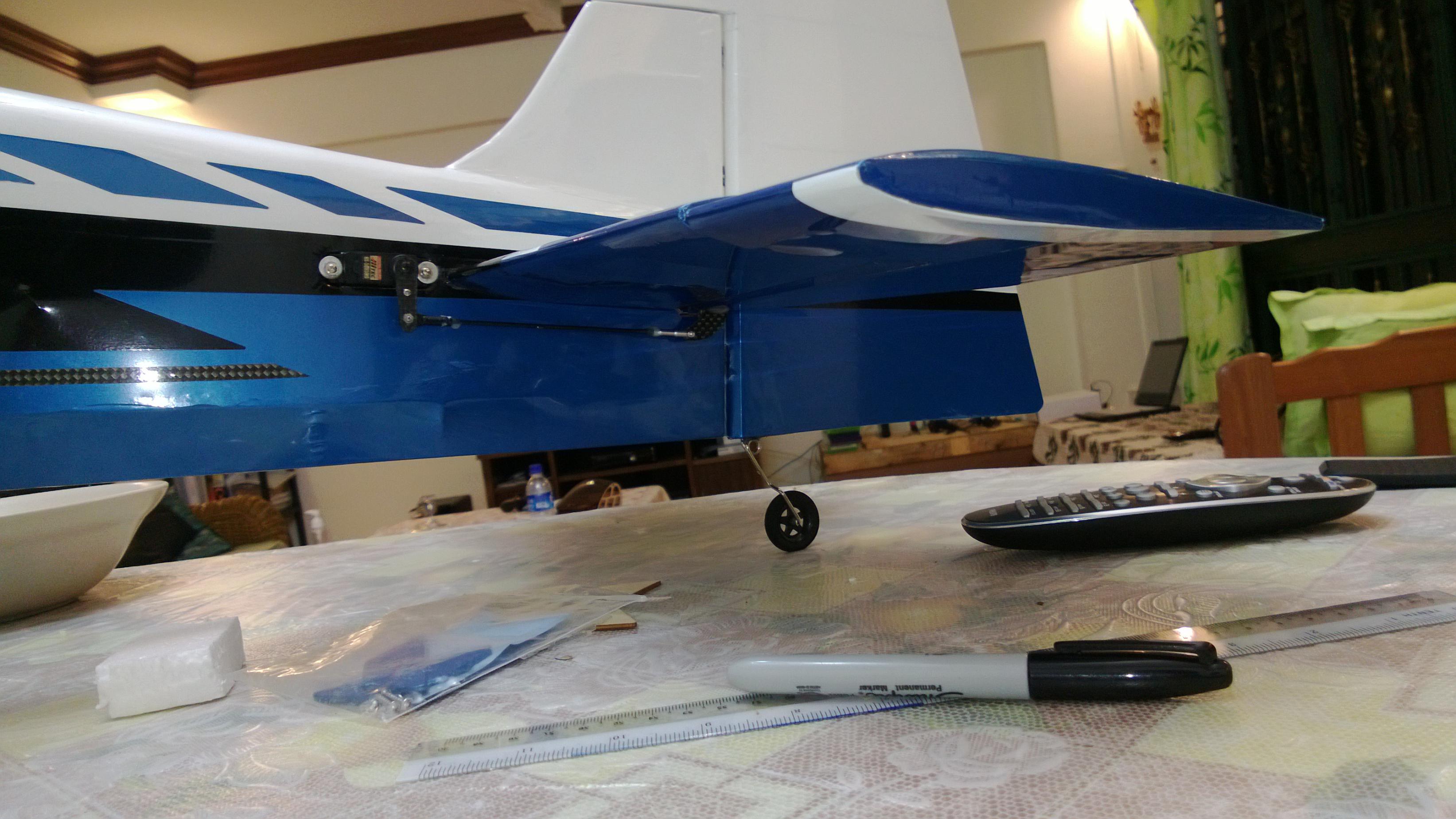
 I am sure it will come out Well .....

Comment