Announcement

Collapse
No announcement yet.

My Recent Scale Heli Project...

Collapse

Zenm Tech Pte Ltd

Collapse

Visit Zenmtech at rc.zenmtech.com

X
 
  • Filter
  • Time
  • Show
Clear All
new posts

    My Recent Scale Heli Project...

    Here is my latest scale project. See whether can you guess what scale heli is it?
    It is still in process of building.

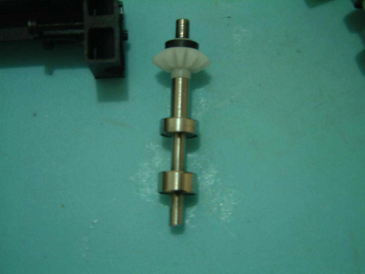
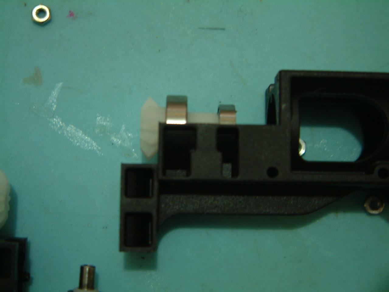
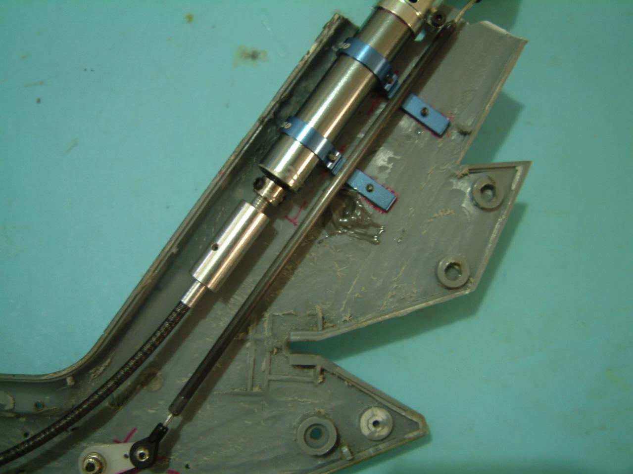
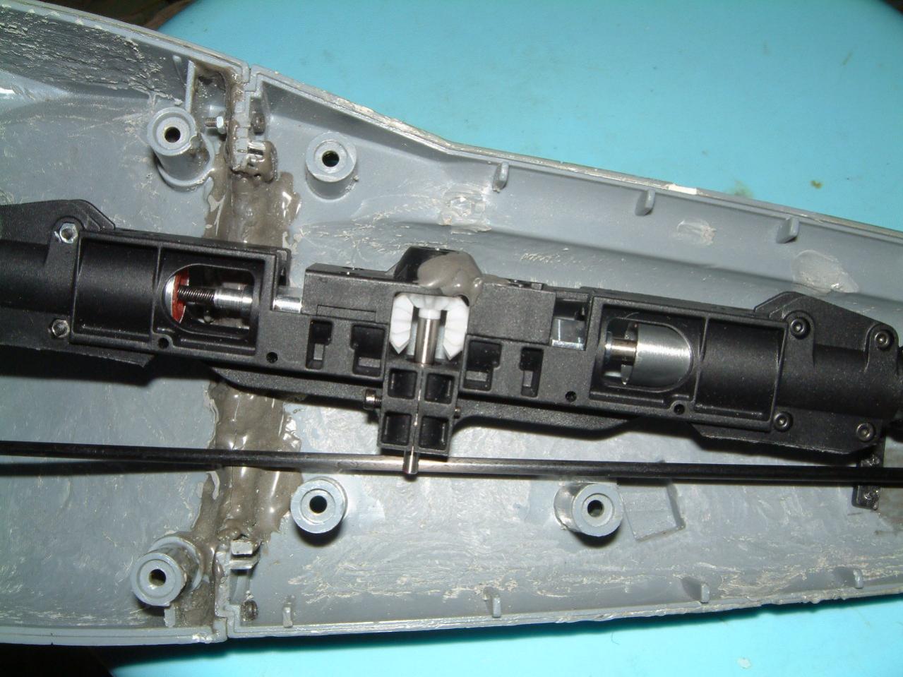
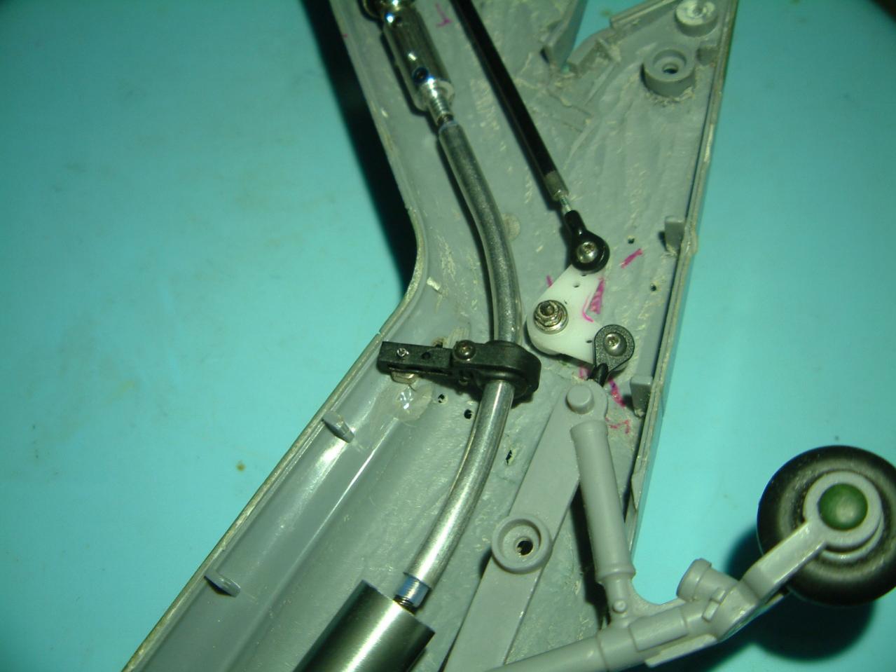
    I am using Mini-Titan heli for this scale. Due to this scale heli is a "low boom" type, that mean I need to modify Mini-Titan (MT) so that to "route" the tail drive downward instead.

    Previously, I was using TRex450 with very long belt to the tail rotor. The problem of this design (Trex450 with belt) is that, when using MXL belt (TRex450 and MT type of belt), when it reaches certain lenght, the belt will "slap" together and also it is weak to drive the tail.
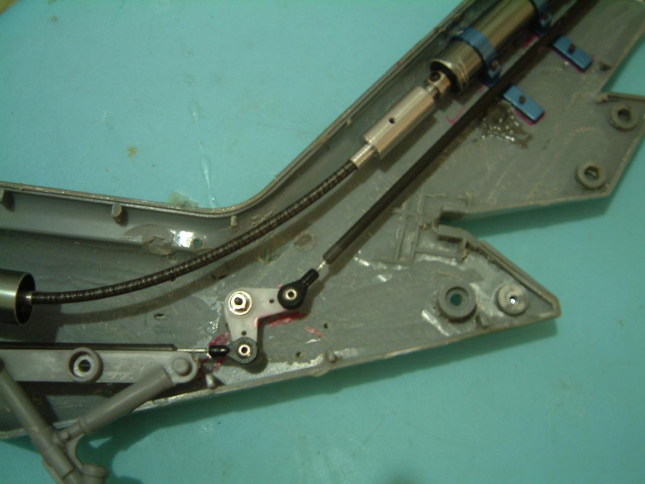
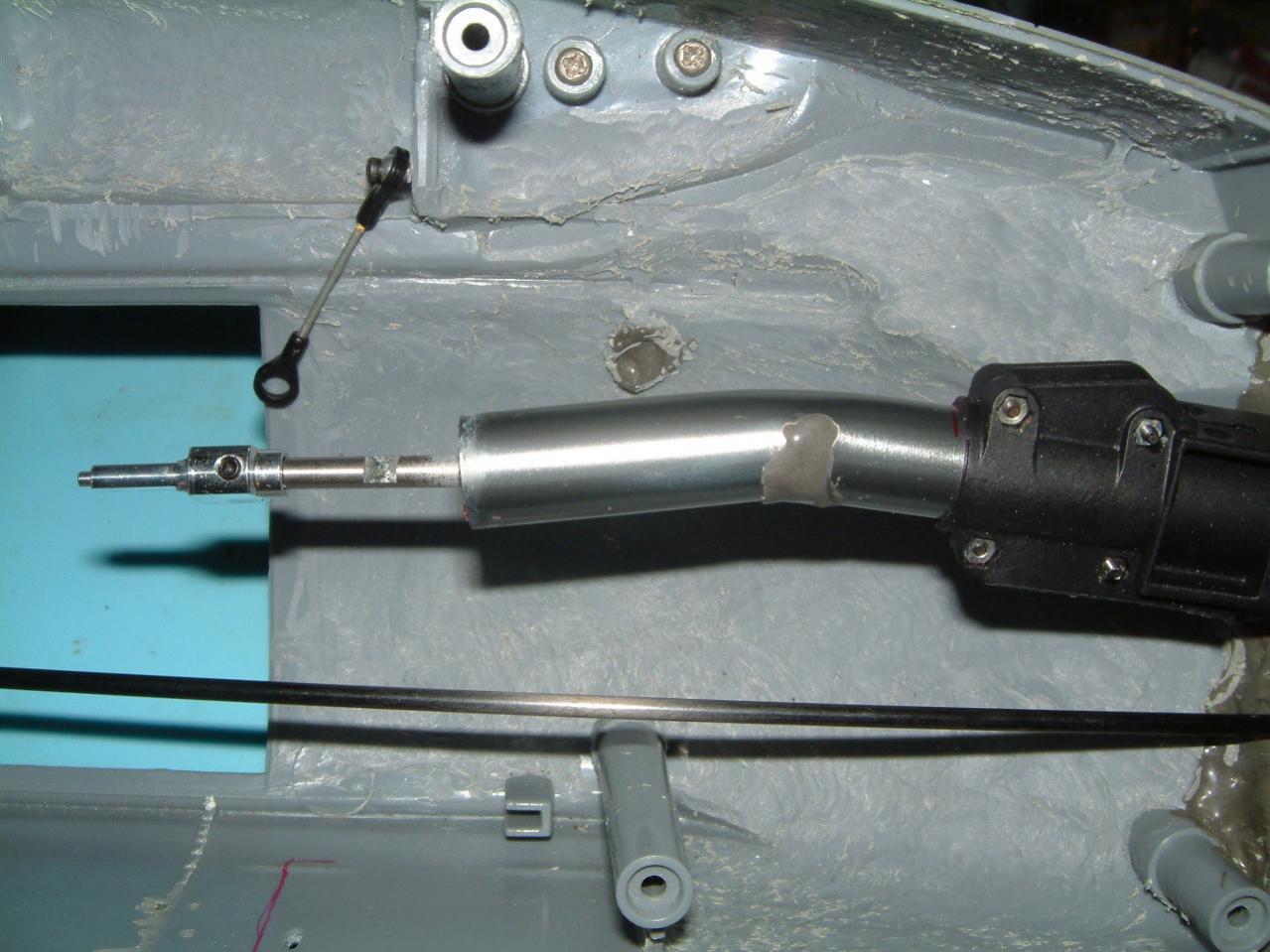
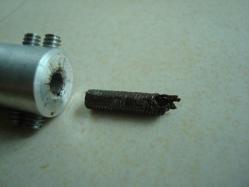
    This time, I decided to use drive shaft method instead. But in this case (due to "low boom" heli), I use flexible cable instead. The normal usage is for R/C Marine (Boat).

    MT's drive shaft is 4mm diameter. I can't find 4mm diameter flex cable in local hobby shop, so I use 3.17mm or 3.18mm diameter flexible cable instead.

    Why I did not use TRex450 Pro (also shaft driven tail), is because TRex450 Pro's main to tail rotation ratio is 1:4. This is considered way too low for multibladed heli. For shaft driven tail, to change tail rotor is to change the bevel gear...which is very difficult to achieve.
    MT's main to tail ratio should be higher than TRex450Pro. That is why I decided to try MT with shaft driven instead.

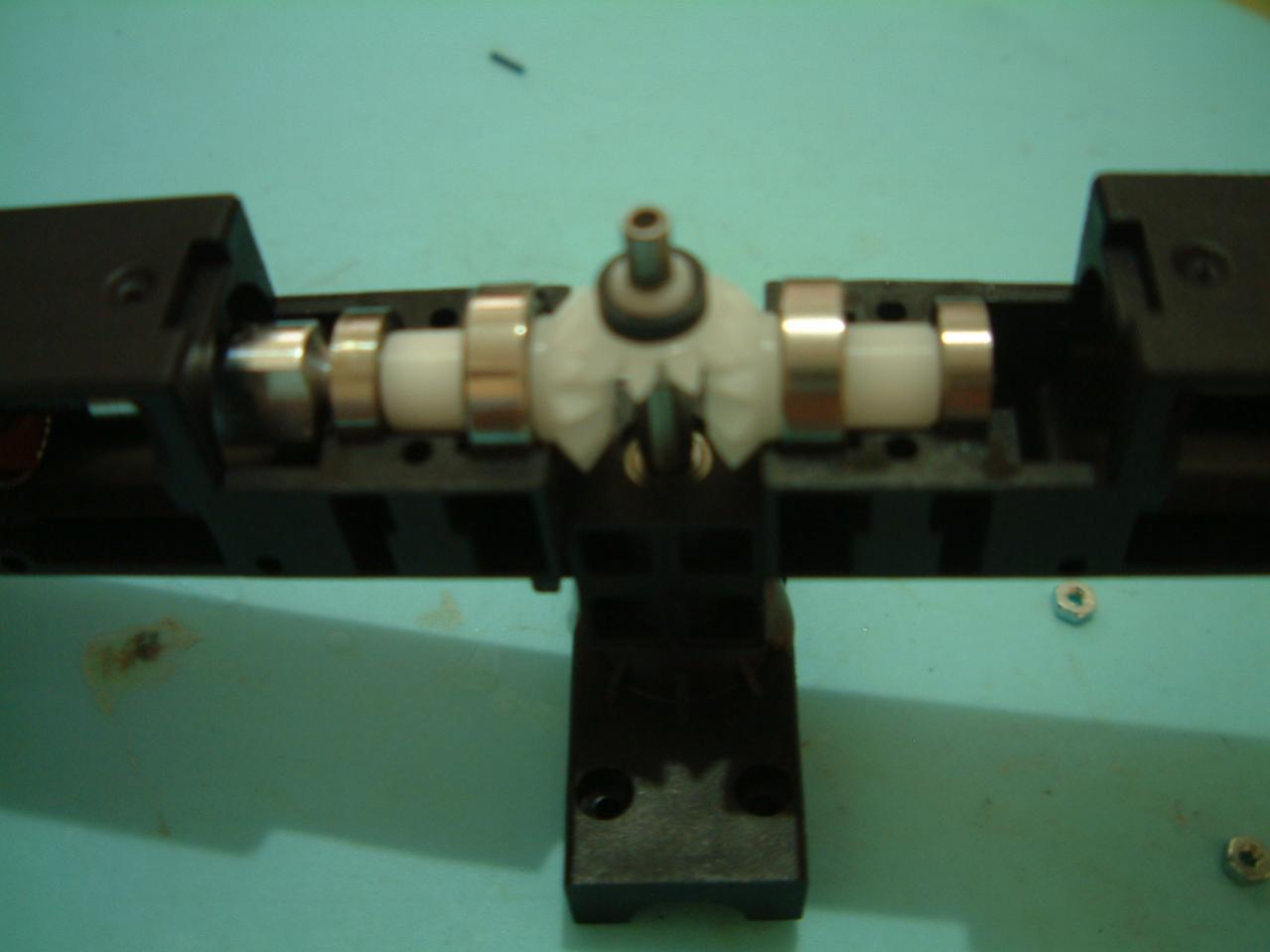
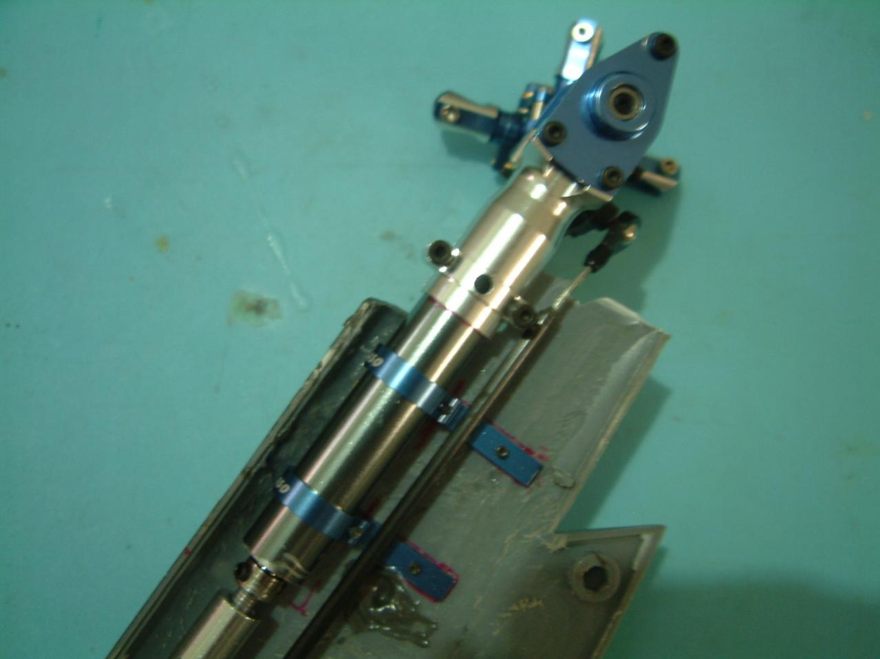
    The scale heli I doing is 4 bladed main rotor, spin at CounterClockWise rotation, 4 bladed tail rotor on the right side of the heli and it is spinning upward.

    By using MT with shaft driven (but in this case, flexible cable), if minicking of main and tail rotor rotation, the tail drive system required to be reverse rotation in order to achive the correct rotation.

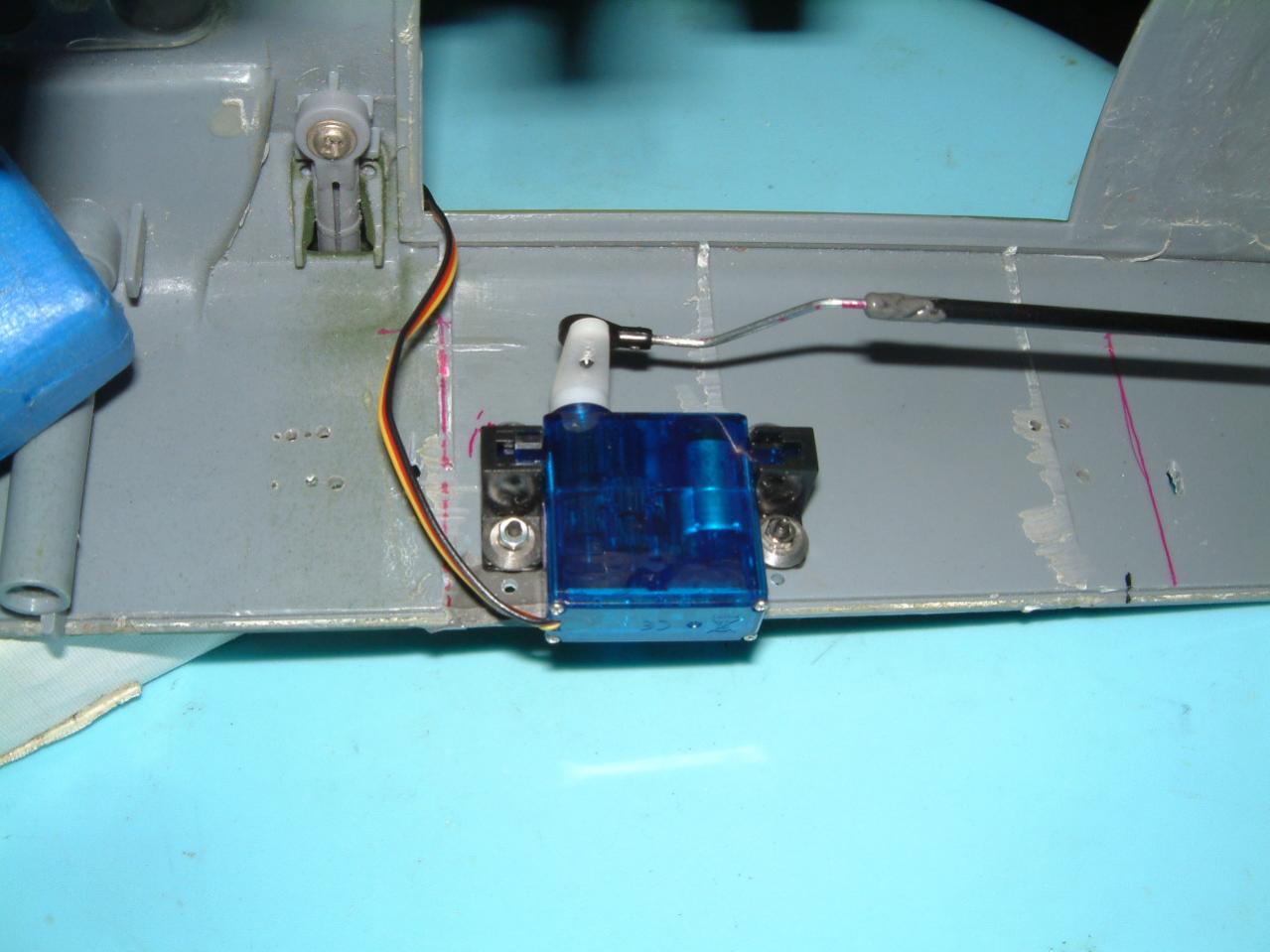
    Here are the photo I took this afternoon.

    SH

    #2
    Photo description
    #1. Modified tail shaft to be use for tail drive direction reversal gearbox.
    #2. One piece of shaft drive base unit.
    #3. Another piece of shaft drive base unit.
    #4. Modified shaft drive base unit cover.
    #5. Putting 2 shaft drive base unit together with the modified tail shaft.

    SH

    Comment


      #3
      Picture info:
      1. One part of the shaft driven system at the boom section.
      2. The exposed flexible cable with the "L" linkage for tail pitch control.
      3. Tail wheel with with tail linkage install.
      4. The elevated tail shaft driving unit. It is TRex450Pro clone part.
      5. Closer look of the elevated tail shaft driving unit.

      Comment


        #4
        Photo info:
        1. Tail rotor gearbox. It is from Tarod (TRex450Pro clone?)

        Comment


          #5
          Bro, is it a UH-60 ?

          Comment


            #6
            blackhawk?
            I love PAP

            Comment


              #7
              You need more support on the flex cable. Use teflon tubing and brass tube and then epoxy the brass tube to the fuselage.

              Comment


                #8
                It is Pave Hawk actually

                Originally posted by Adrianli View Post
                You need more support on the flex cable. Use teflon tubing and brass tube and then epoxy the brass tube to the fuselage.
                i did try with teflon tubing and aluminium tubing over the teflon before. test spinning up with and without make no different. Maybe due to the exposed section is short. But notice using exposed has lesser friction so i decided to go without.

                SH

                Comment


                  #9
                  Some more photo:

                  1. Placement/location of tail servo. I only have Hitec HS-A5076HB with me right now so temporary use it for tail. See whether can it handle the tail rotor or not. If not, need to replace it.
                  2. Shaft driven reversal gearbox. One side connected to the shaft drive on the tail.
                  3. Reversal gearbox closed up.
                  4. The other end of the reversal gearbox that is going to the MT body. Notice the linkage on the fuselage? that is to support the MT body to the fuselage. It is one of the support linkages. Need it in order to prevent the top part of the heli (or the rotor head) from wobble.

                  SH

                  Comment


                    #10
                    Just for extra information... It is possible to create tandem rotor helicopter using 2 Mini-Titan body, some shaft driven conversion kit and the above "Reversal Gearbox"!

                    Sometime back, I did created a tandem rotor helicopter using 2 TRex450 and connect/synchronize the 2 rotors using belt but because of belt behavior, when main rotor pitch increases, the belt will slip and 2 rotor will hit each other.

                    By using shaft driven, it should not have "belt slipping" problem

                    Anyone want to start building a tandem rotor Mini-Titan heli?

                    SH

                    Comment


                      #11
                      Originally posted by Super-Hornet View Post
                      i did try with teflon tubing and aluminium tubing over the teflon before. test spinning up with and without make no different. Maybe due to the exposed section is short. But notice using exposed has lesser friction so i decided to go without.

                      SH
                      Too much free-play for flex cable is no good. It will eventually lead to material fatigue and the flex cable will snap!!! Once flex cable snaps, it will cause lots of damage.

                      I have been using flex cable since my boating days, and have snapped a few to know.

                      You have been warned.


                      BTW, have you run the setup as it is on full speed???

                      Comment


                        #12
                        Some of my past experiences. 
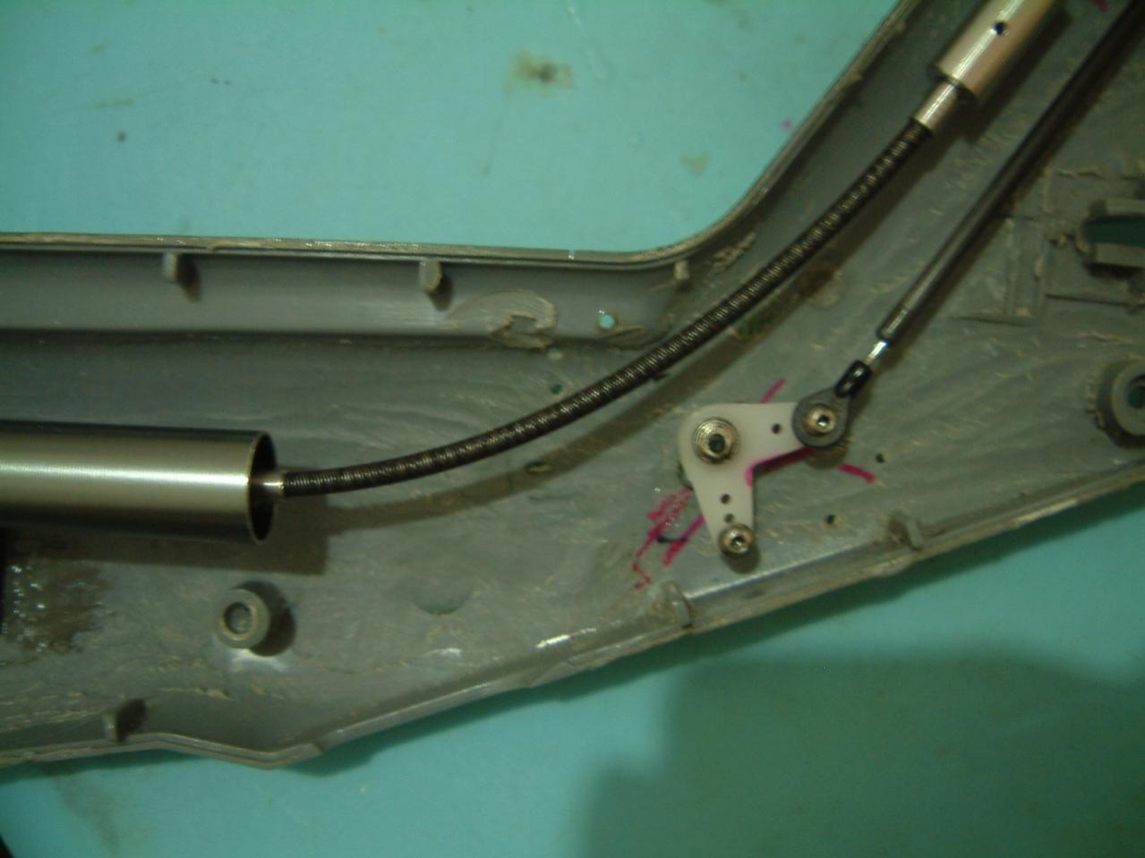
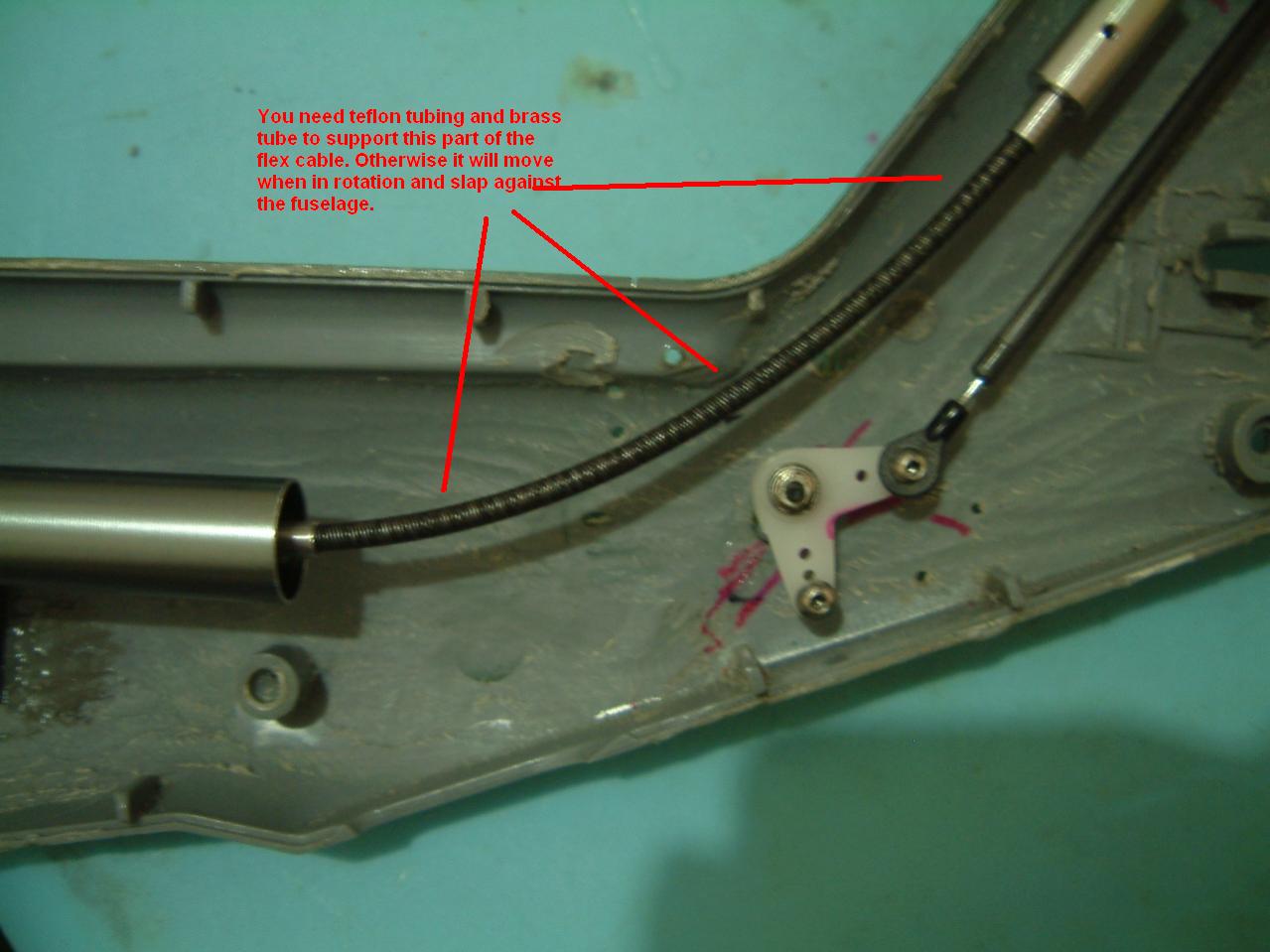
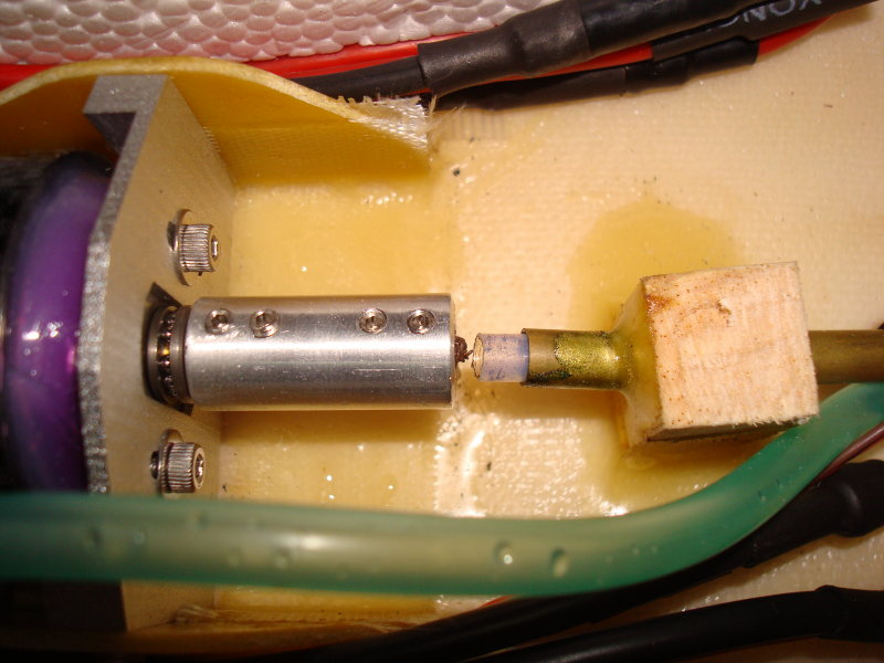
BTW I run my flex cables at ard 30,000rpm.

                        Comment


                          #13
                          Originally posted by Super-Hornet View Post
                          Picture info:
                          1. One part of the shaft driven system at the boom section.
                          2. The exposed flexible cable with the "L" linkage for tail pitch control.
                          3. Tail wheel with with tail linkage install.
                          4. The elevated tail shaft driving unit. It is TRex450Pro clone part.
                          5. Closer look of the elevated tail shaft driving unit.
                          I've bookmark this build thread.

                          Super-Hornet, did you custom make the flexdrive coupling ? Did you have to solder the flexdrive cable yourself ?

                          Can't wait to see your MH-60 maiden flight video

                          Comment


                            #14
                            Originally posted by hagenuk View Post
                            I've bookmark this build thread.

                            Super-Hornet, did you custom make the flexdrive coupling ? Did you have to solder the flexdrive cable yourself ?

                            Can't wait to see your MH-60 maiden flight video
                            Thanks for the interest "hagenuk".

                            Right now, I tuning the MT with Beastx unit. I just build another tail boom (shaft driven) in order to fix into the MT so I can test fly it barebone in order to properly tune up the BeastX unit.

                            All the above parts are can be purchase/get from LHS or from online shop. Parts are all from MT and TRex450. The coupling that link the flexible cable and the rigid shaft can be get from LHS under R/C marine section.

                            One portion of the flexible cable has a metal rod attached to it. So I do not need to modify it except cut off the screw track (not required for me). The other end of the flexible cable, I cut using dremel but cool it down using water damped tissue paper during cutting. After cut it, I apply loctite instead. The loctite should be able to flow into the flexible cable and fasten it (Use green colored loctite). The coupling is 4mm diameter hole. Flexible cable is 3.18mm. So, I cut a short 4mm aluminium tubing with hole for the set screw to pass through and slot into the coupling. The coupling act as a spacer in order to balance/stabilize the flexible cable.

                            EDIT: The aluminium tubing is loctite to the coupling 1st and let it dry before inserting the flexible cable. Again, use green colored loctite.

                            SH

                            Comment


                              #15
                              Did some modification of the flexible cable for the "exposed" area.
                              Aluminium tubing over Teflon tubing. The tubing is clamp using E-Sky's tail servo mounting clamp. The rubber "O-Ring" is to dampen the vibration coming from the tubing so it does not get transferred to the fuselage.

                              I wanted to mount 2 clamps for the tubing but not enough space to screw the 2nd clamp. So, I leave it as 1 clamp 1st.

                              The inner tubing (teflon) is filled with translucent grease.

                              SH

                              Comment

                              Working...
                              X