usually, the reference of PWM circuit in a PC PS attach on +5V. since most of RC Charger need 12V or higher, you have two ways to do:
A: simple way:
1. enable the PS. if it is a old AT PS, no need to enable, just power up. if it is a ATX, short pin 14(power on, green color) to ground. just short 14-15 or 13-14, because 13 and 15 are commom ground.
2. add a dummy load on +5V, you and use a 6V 15W light bulb ar even a high power resistor to make sure there is about 2A on +5V. calculate the value of resistor:
V=5v, I=2A, R=V/I= 5/2=2.5 ohm.
V=5v, I=2A, P=VI= 5X2=10W.
so we need a 2.5-3 ohm, 15W resistor as a dummy load. try to touch the resistor to metal casing. it will be hot while the PS is working.
with this dummy load, the problem of vlotage drop while a heavy load applied will be insignificant.
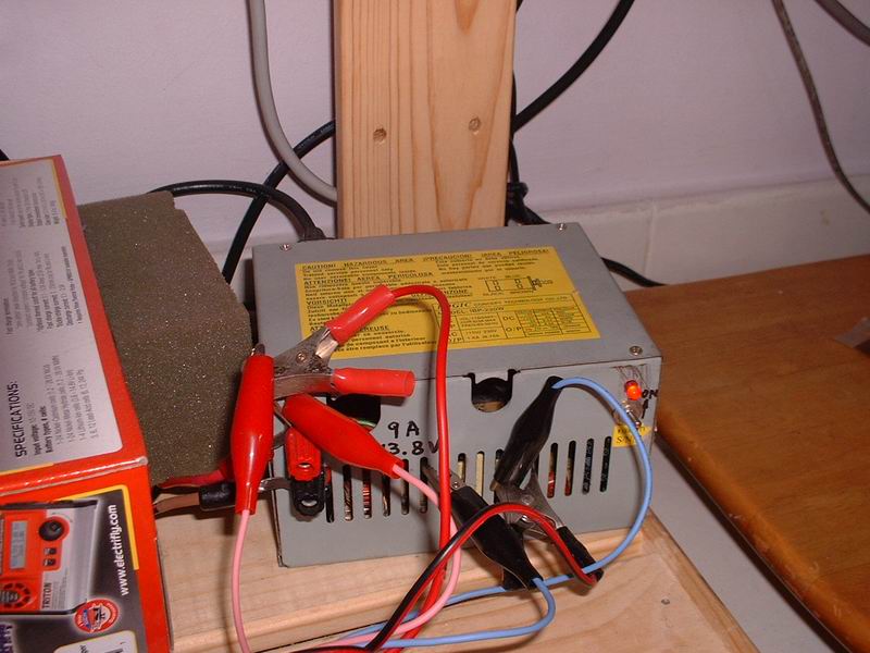
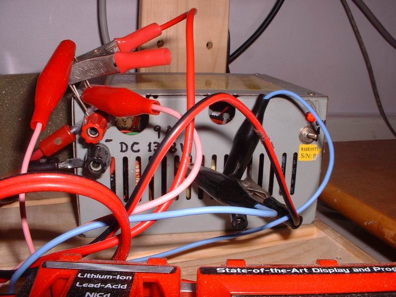
3. wire up the PS, connect 12V output to charger, install a switch and a LED...remember you need a current limiting resistor to connect series with LED, otherwise the LED will just burn out when you switch on. around 330ohm will do, depends on how light the LED you want.
A: simple way:
1. enable the PS. if it is a old AT PS, no need to enable, just power up. if it is a ATX, short pin 14(power on, green color) to ground. just short 14-15 or 13-14, because 13 and 15 are commom ground.
2. add a dummy load on +5V, you and use a 6V 15W light bulb ar even a high power resistor to make sure there is about 2A on +5V. calculate the value of resistor:
V=5v, I=2A, R=V/I= 5/2=2.5 ohm.
V=5v, I=2A, P=VI= 5X2=10W.
so we need a 2.5-3 ohm, 15W resistor as a dummy load. try to touch the resistor to metal casing. it will be hot while the PS is working.
with this dummy load, the problem of vlotage drop while a heavy load applied will be insignificant.
3. wire up the PS, connect 12V output to charger, install a switch and a LED...remember you need a current limiting resistor to connect series with LED, otherwise the LED will just burn out when you switch on. around 330ohm will do, depends on how light the LED you want.


Comment